Asus K50IJ Charging Port Replacement
ID: 100301
Description: Charging port pieces inside of the laptop may...
Steps:
- Slide the tab over to unlock the battery cover located on the bottom-left corner of the laptop.
- Lift the exposed lip and remove the battery cover.
- Press the tabs on the battery and lift them. The battery should come out easily.
- Using the PH1 screwdriver, remove the four 4 .75 mm screws that are located on the vent panel.
- Remove the one .5 mm screw located in the top right corner of the battery compartment.
- Remove the bottom panel by sliding it toward the hinges and lifting the back panel up.
- Unplug the wire cable attached to the fan by pulling it out .
- Using the PH1 screwdriver, remove the 3 .75mm screws labeled as 1, 2, and 3 on the fan. NOTE these screws have the labels "1", "2", and "3" next to them.
- Lift the fan up with your fingers.
- Using the PH1 screwdriver remove the two .75 mm screws from the hinge side of the laptop.
- Using the PH1 screwdriver, remove the four .75 mm screws from the copper heat sync. They will be labeled 1-4.
- Pull the copper heat sync out of the laptop.
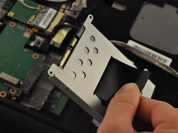
- Using the PH1 screwdriver, remove four .75 mm screws from the driver, located in the bottom-right corner of the laptop.
- Pull on the black tab on the driver to slide the driver back, and lift the driver out of the laptop.
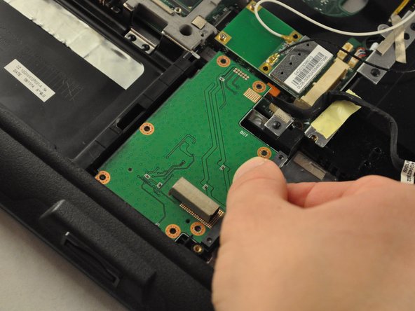
- Using the PH1 screwdriver, remove the five .5 mm screws from the SD card reader, located in the bottom-middle corner of the laptop.
- Slide the SD card reader away and out.
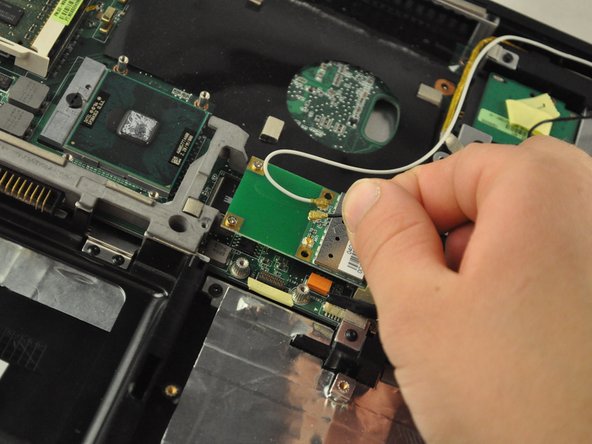
- Detach the white and black wires from the Wi-Fi card, located in the central area of the laptop.
- Using the PH 1 screwdriver, remove the two .25 mm screws from the Wi-Fi card.
- Slide the Wi-Fi card out of its slot to remove.
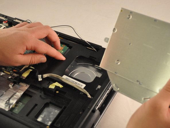
- Using the PH1mm screwdriver, remove one .5 mm screw from the disk drive, located inthe top-right corner of the laptop.
- Slide the disc drive out of its slot.
- Using the PH 1 screwdriver, remove the two .5 mm screws from the RAM drive.
- Slide and lift the RAMdrive out of its port.
- Using the PH1 screwdriver, remove the .75 mm screw from the plastic housing corner, located in the bottom-right corner of the laptop.
- Unplug the black cable from the central area of the laptop.
- Unplug the wire cable in the central area of the laptop.
- Unplug the wire and black cables on the motherboard, located in the upper-left corner of the laptop.
- Using the PH1 screwdriver, unscrew the two .75 mm screws from the top-left corner of the motherboard.
- Using the PH 1 screwdriver, remove the .75 cm screw from the top-middle section of the motherboard.
- Using the PH1 screwdriver, remove the .75 mm screw from the top-middle corner of the motherboard.
- Using the PH1 screwdriver, remove the three .75 mm screws from the bottom corner of the motherboard.
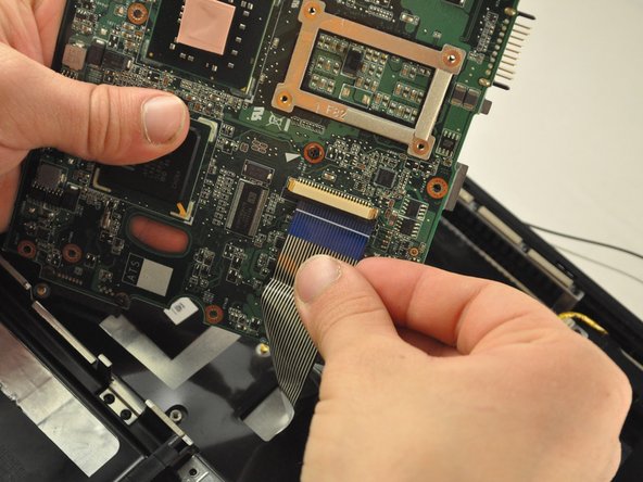
- There is a ribbon cable connected to the back of the motherboard. Be careful not to break the ribbon cable.
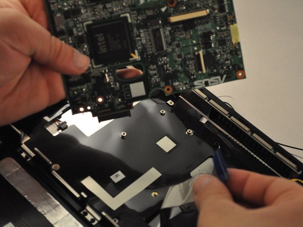
- Slide the motherboard to the right and lift it up, but do not pull it completely out.
- Gently unplug the ribbon cable from the underside of the motherboard.
- The ribbon cable that was plugged into the motherboard is attached to the keyboard. Be sure not to damage it.
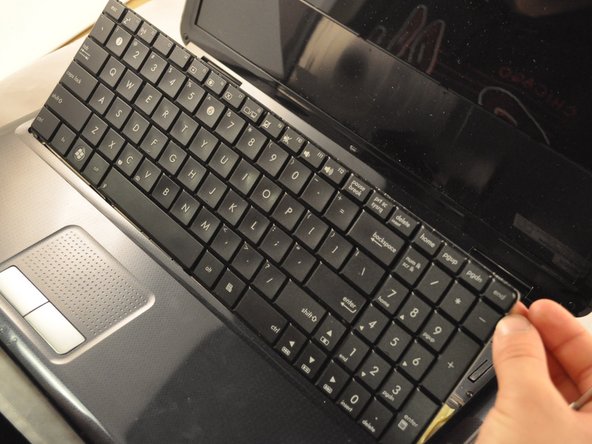
- Use the metal spudger or opening tool across the top edge of the keyboard to pop it out.
- Use the metal spudger or opening tool to pop out the plastic hinge covers.
- Use the PH1 screwdriver to remove the .75 mm screws from the hinges. Each hinge has one screw.
- Be careful not to damage the cables that are attached to the screen frame. Be sure to pull them through the laptop carefully.
- The screen should separate from the rest of the laptop.
- Using the PH1 screwdriver, remove the .75 mm screw from the bottom-middle section was previously covering.
- Using the PH 1 screwdriver, remove the .75 cm screw from the bottom-middle section where the keyboard was previously covering.
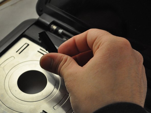
- Lift the front cover off of the laptop.
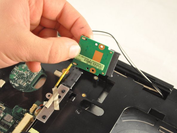
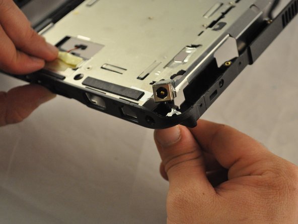
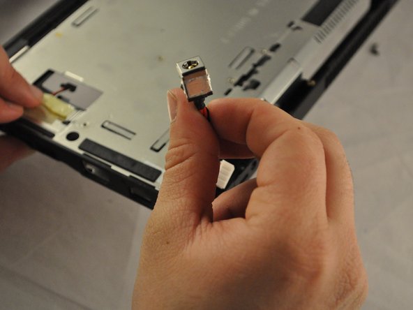
- Flip the laptop back over. The charging port will be located in the top-right corner.