Acer Aspire E1-510-2500 Webcam Replacement
ID: 100465
Description: If your webcam has stopped working or has been...
Steps:
- Ensure that your laptop is completely switched off, and disconnected from the power source.
- Flip the laptop so that the base of the laptop is facing up.
- Insert a spudger into the battery release latch.
- Slide the battery release latch to the right, this will eject the battery for safe removal.
- Carefully slide the battery out of the battery's home.
- Using a Phillips 1 screwdriver, remove the 17 9mm screws from the bottom of the laptop, including the one in the back panel.
- Using a plastic opening tool, carefully remove the back panel.
- Remove the 9mm screw under the back panel.
- When reassembling, insert the panel from the bottom edge first.
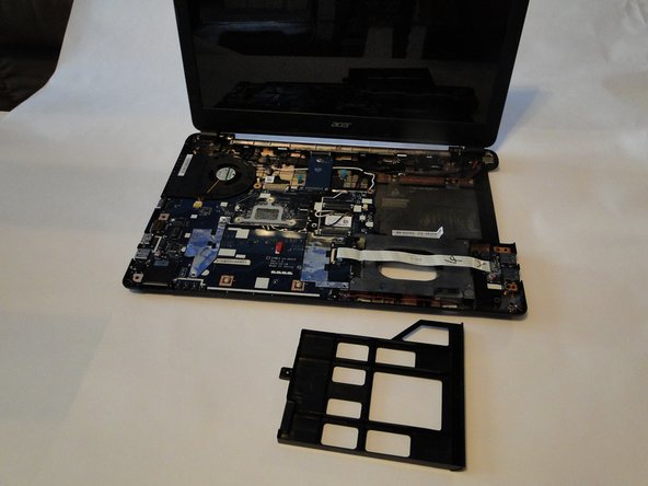
- Using a plastic opening tool, carefully separate the frame along the edges of the laptop. This should separate the keyboard assembly from the bottom portion of the laptop.
- Open the laptop, leaving the screen flat on the table.
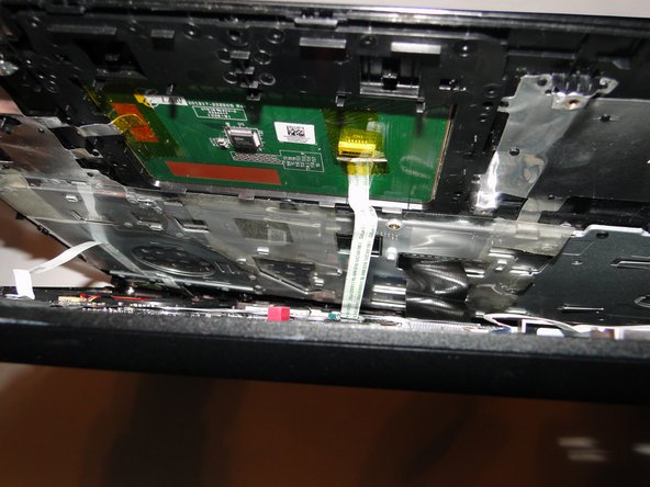
- Carefully pull the keyboard assembly out away from the base of the laptop. There should be three connections visible in the gap between the keyboard assembly and the base.
- Using tweezers, carefully detach the connections from the base.
- Place the keyboard assembly and disk tray place holder aside.
- For reassembly, leave the disk tray place holder out until after the blue tape connector has been reconnected, to have enough space to reattach the tape.
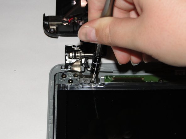
- Locate the backs of the hinges and remove the two 4mm screws using a Phillips 1 screwdriver. If this is the first time removing these screws, there will be a black covering over each screw. The black covering can be removed with a pair of tweezers.
- Lay the laptop base down with the screen still open.
- Detach the wire connection from the screen to the motherboard.
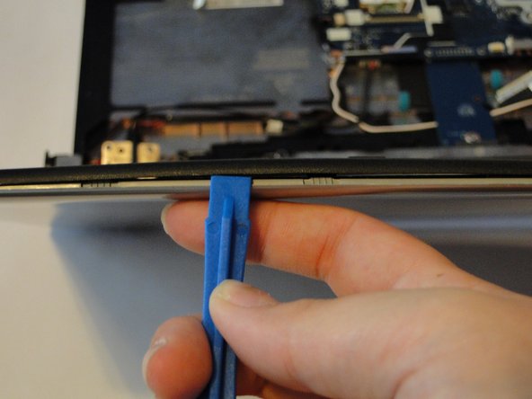
- Using a plastic opening tool, carefully separate the front bezel from the top case.
- Remove the five 5mm screws on the hinges using the Phillips 1 screwdriver. This will release the laptop screen from the base, so be sure to brace it against something so that it does not fall.
- Lay the screen flat on the table. There should still be two wires on each side in or around the hinges that go from the top portion to the base.
- Remove the six silver 3mm screws from the screen attachment points using a Phillips 1 screwdriver.
- Remove the four black 3mm screws from the screen attachment points using a Phillips 1 screwdriver.
- Detach the wire connection for the camera.
- Carefully move the wire attached to the screen out of the hinge.
- Remove the screen.
- Be careful of the LED attached at the base of the screen because it is not immediately noticeable and can be easily damaged.
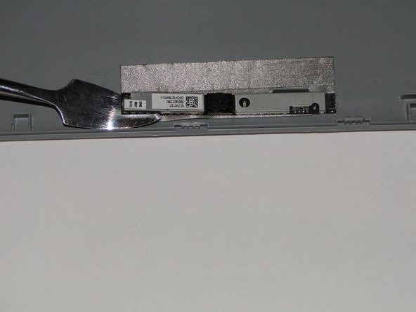
- Carefully detach the camera from the back bezel using a spudger and careful upward pressure.
- Glue is required to reattach the camera to the frame.