Carrera Mario Copter Motor Replacement
ID: 100475
Description: A weak or damaged motor might be the reason...
Steps:
- Flip the quadrocopter over so that the underside of the device is facing up.
- Unplug the battery cable from the socket on the quadrocopter.
- Push the battery upward with your thumbs to loosen it from the tight slot until your thumbs can not reach the bottom of the battery anymore.
- Pull the battery away from the slot to remove it.
- Using the JIS #00 screwdriver, hold the rotor blade still and unscrew the 4.762mm screw in the center of the blade.
- Lift the screw out and set it aside.
- Lift the rotor blade out.
- Be sure to place the rotor blades properly for stable flight. With the quadrocopter facing you, the front rotor blades should be red with blade A on the right and B on the left. The rear rotor blades should be blue with blade B on the right and A on the left.
- With the PH1 screwdriver, unscrew the four 7.1mm screws located underneath the quadrocopter.
- Pull the base out and set the foam piece aside
- From the precision tweezers set, use the round-end tweezers to pull and wiggle the white-head wires from the motherboard.
- Be sure to pull from the connector. Otherwise you run the risk of slicing through the wires.
- Using the PH0 screwdriver, unscrew the 3.2 mm screw on the base.
- While all four locations are shown, you will only have to remove the screw/s corresponding to the motor/s you are replacing.
- Pull the rotor leg out from the base
- Using the PH0 screwdriver, unscrew the 4 mm screw where the leg meets the motor case/ rotor stand.
- Pull the leg apart from the motor case/ rotor stand
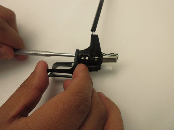
- Using the metal spudger of your choice, remove the clip at the top of the motor.
- Use the thinner side of the spudger to push the motor through and out of the case.
- Cut the connection head off and pull the wiring out of the leg.