HP G62-144DX Motherboard Replacement
ID: 100487
Description: If the motherboard is not working correctly, it...
Steps:
- Make sure to turn off the laptop before removing the battery.
- Slide the lock to the right, located slightly above the battery location.
- While pulling the lock, pull the battery out, keeping it flat and parallel to the laptop so that it slides out easily.
- Loosen the 2 Phillips 2.5x6 screws in the rectangular panel with a Phillips #1 screwdriver.
- The screws will stay in the panel, but come free from the body of the computer.
- Gently remove the panel with a plastic opening tool.
- Unscrew the three 3x4 Phillips screws holding the hard drive in with a Phillips #1 screwdriver.
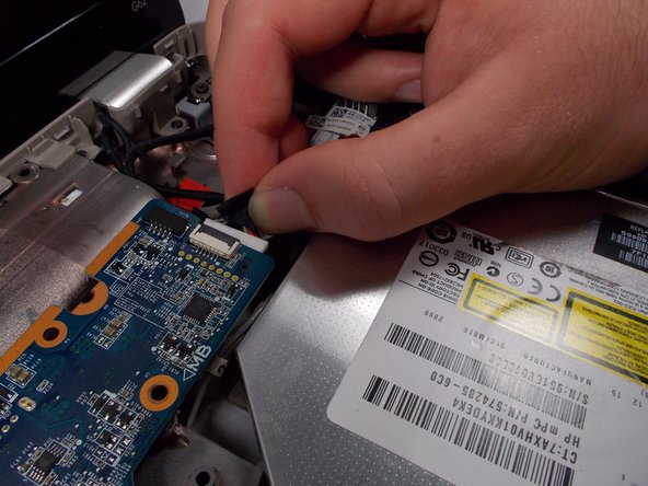
- Pull the hard drive cable out of the motherboard.
- Pull the hard drive out of the computer.
- Unscrew the three Phillips 2.5x6 screws in the L-shaped panel on the back with a Phillips #1 screwdriver.
- The screws will stay in the panel, but will come loose from the body of the laptop.
- Use a plastic opening tool to gently pry the panel free from the laptop.
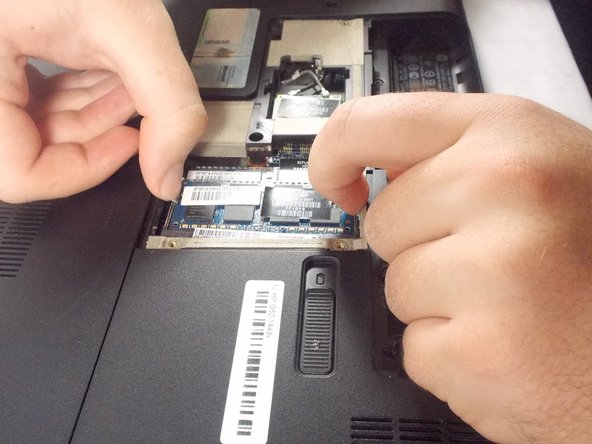
- Pull the two metal clips to the top RAM module outwards parallel to the laptop.
- After the RAM module pops up, gently pull in out from the computer.
- Repeat for the second RAM module.
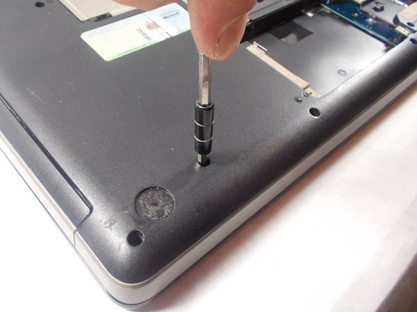
- Remove the 3 Phillips 2.5x5 screws (closest to the battery slot) and the 2 Phillips 2.5x6.5 screws with a Phillips #1 screwdriver.
- This screws will have a keyboard symbol inscribed next to them.
- Use the Phillips # 1 screwdriver to unscrew the 2.5x6 Phillips screws holding the L-shaped back panel.
- Screws should stay in panel, but come free of the laptop body.
- Gently use a plastic opening tool to remove the panel.
- Unscrew the final Phillips 2.5x5 keyboard screw with a Phillips #1 screwdriver.
- Flip the laptop so the top is facing up again and open the cover.
- Use a metal spudger to pry the keyboard up and pull it back.
- Be sure to pry up the board itself and not an individual key.
- This process has the risk of breaking keys.
- Pull up the latch that connects the keyboard connector the the motherboard.
- Remove four Phillips PM2.5x3 screws in the battery bay, and remove ten Phillips PM2.5x6.5 screws on the base enclosure with a Phillips #1 screwdriver.
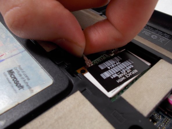
- Remove the Phillips PM2.0×3.0 screw that secures the WLAN module to the computer with a Phillips #0 screwdriver.
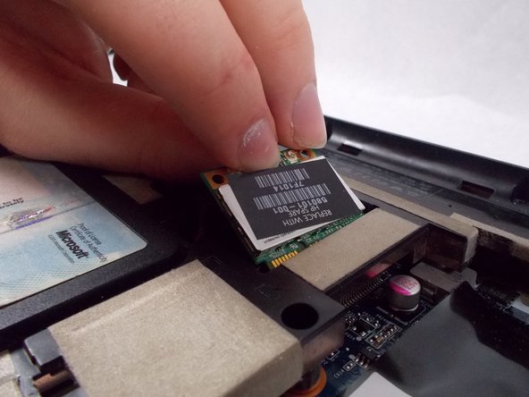
- Disconnect the two wires that attach the card to the motherboard by pulling them up individually.
- Grab the card gently and pull it out after it pops up.
- Flip the laptop over so that the top is facing upwards.
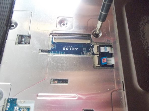
- Remove the Phillips PM2.5×6.0 screw that secures the top cover to the computer with a Phillips #1 screwdriver.
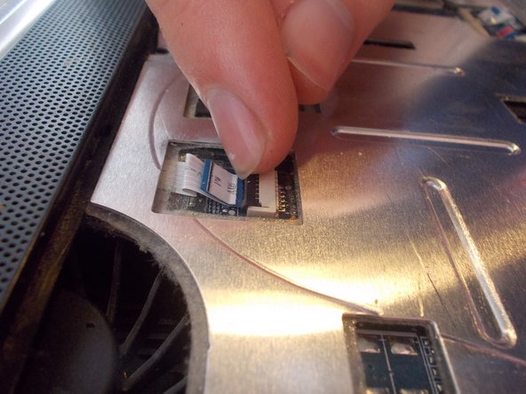
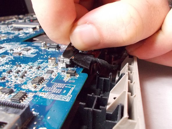
- Disconnect the 4 connectors to the motherboard.
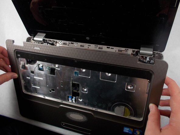
- Take off the cover by prying open the cover with a plastic opening tool.
- Lift the edge near the display first until it pops out, and then remove the cover by pulling it out.
- The cover should come out with ease. If you having trouble pulling the cover out you should double check to see if any screws were left unscrew.
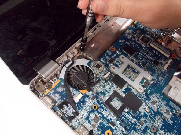
- Remove the two motherboard screws and the fan screw that holds it on the the rest of the computer with a Phillips #1 screwdriver.
- Remove the six connectors from the motherboard.
- The power connector is located underneth the USB connector.
- Lift up the right side of the motherboard and pull it out to the right carefully.