Valve Nodes Teardown
ID: 103304
Description: In this teardown, you will be shown how to take...
Steps:
- You will need 2 small screwdrivers 2 large screwdrivers
- 2x flat head
- One ~5/64
- One ~ 1/2
- 2x Phillips
- One #1
- One #2 ( x 4)
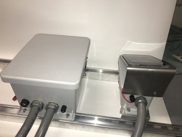
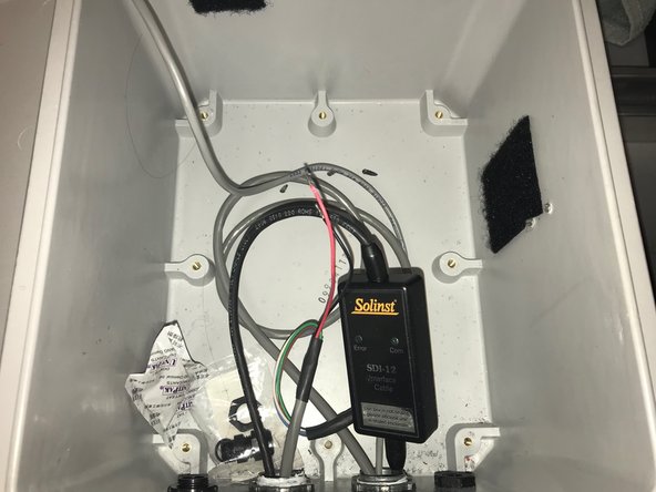
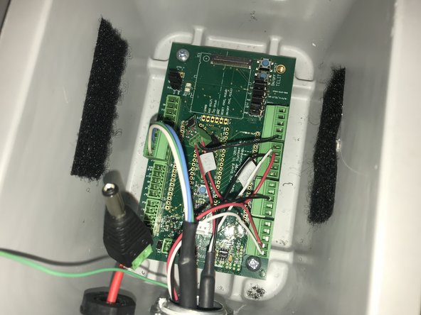
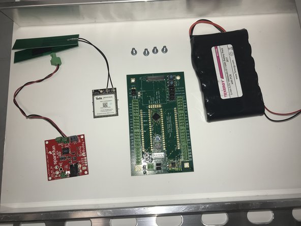
- Here we can see the two fully built nodes for the valve. We will use this as the starting point for our teardown.
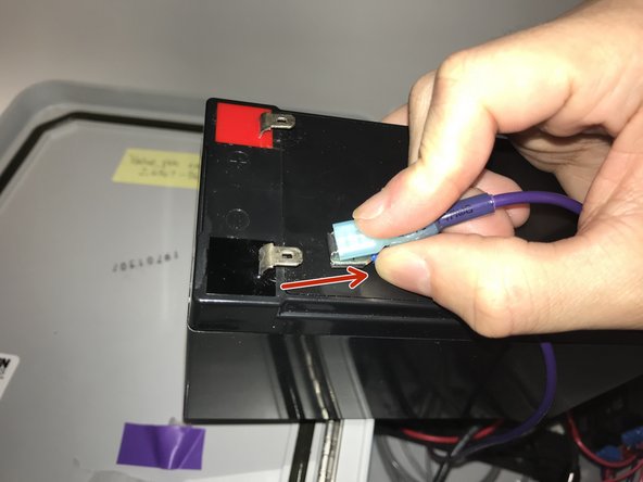
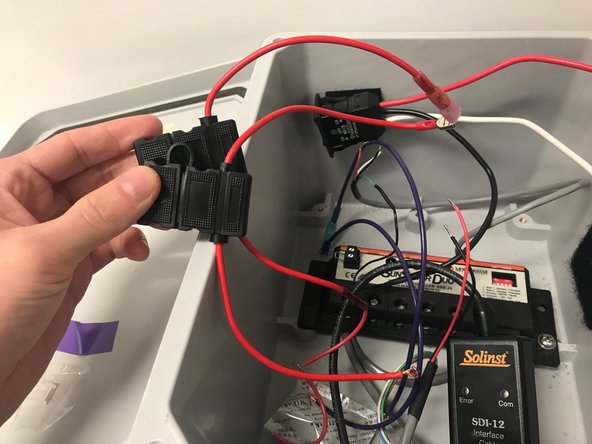
- For the large node unclip the battery
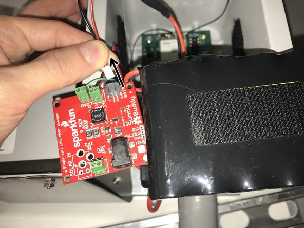
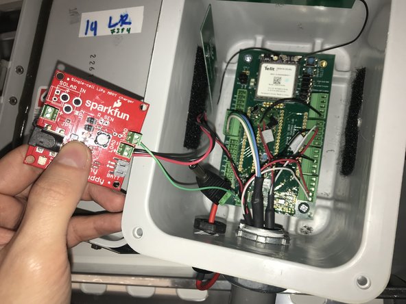
- For the smaller node, detach the battery from the solar charger
- Ensure battery is disconnected
- You will use both types of (small) screwdrivers
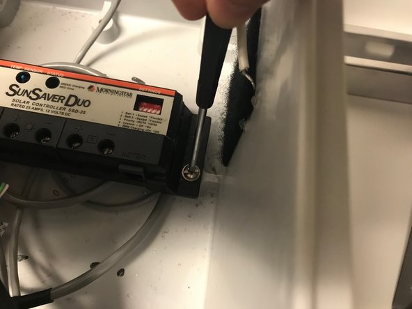
- Use the (large) flat head screwdriver
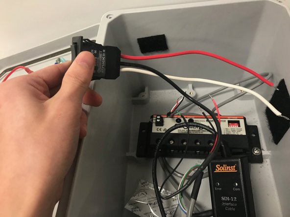
- The switch will most likely still be connected to the small node and will not be able to be fully removed. We recommend removing it from the enclosure to make it tidy
- Use the (large) Phillips screwdriver
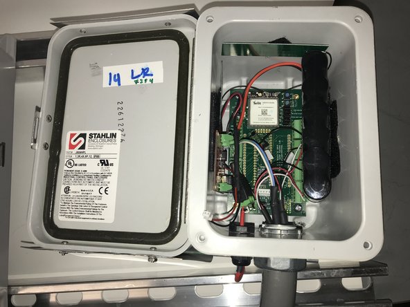
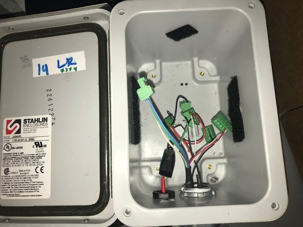
- We have provided a picture of the inside of the enclosure to depict what will still remain inside
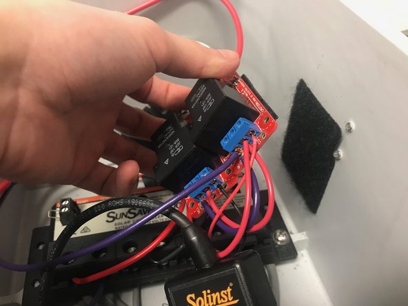
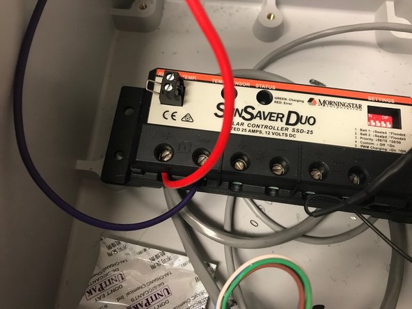
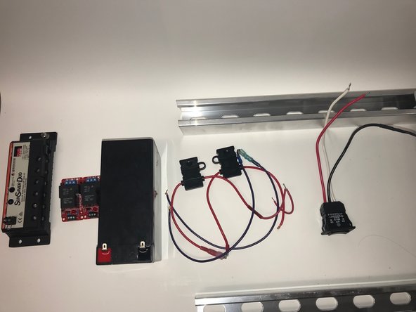
- With the interior of the large node removed, these are the components we have (from left to right):
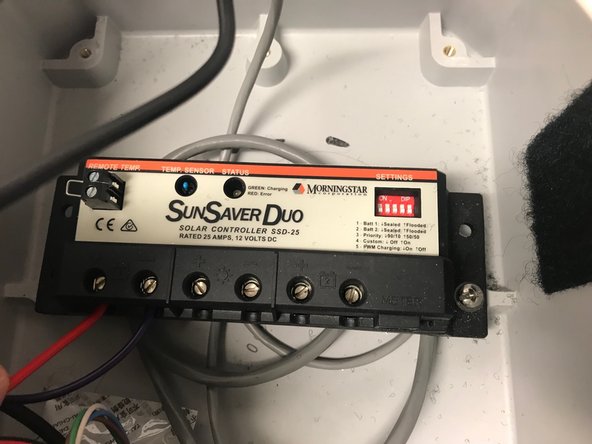
- SunSaver Duo
- Relays
- Battery
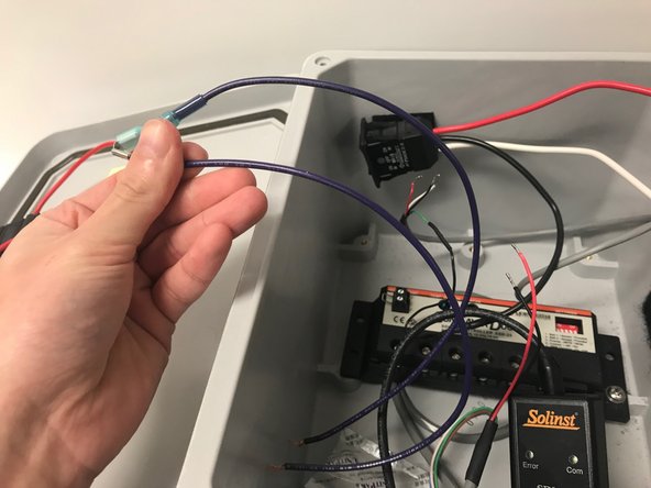
- Battery Wires/Connectors
- Switch (still connected to the small enclosure via the conduit)
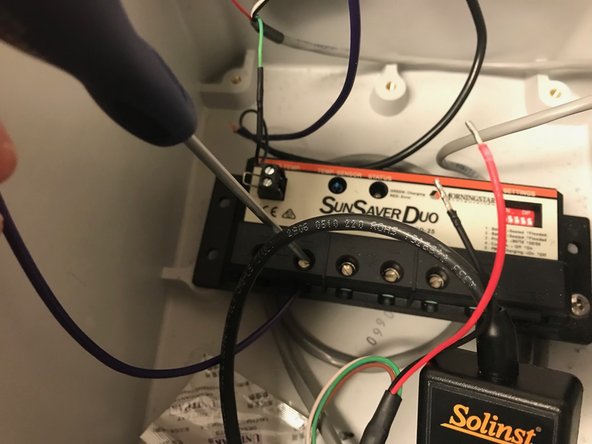
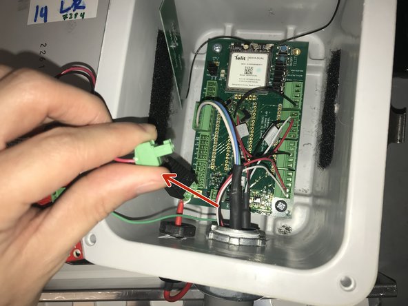
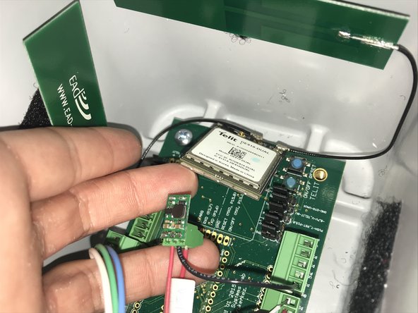
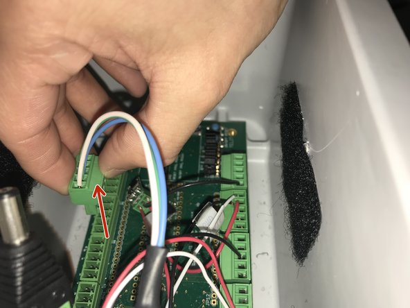
- With the battery removed, our first step will be to remove the solar charger:
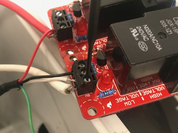
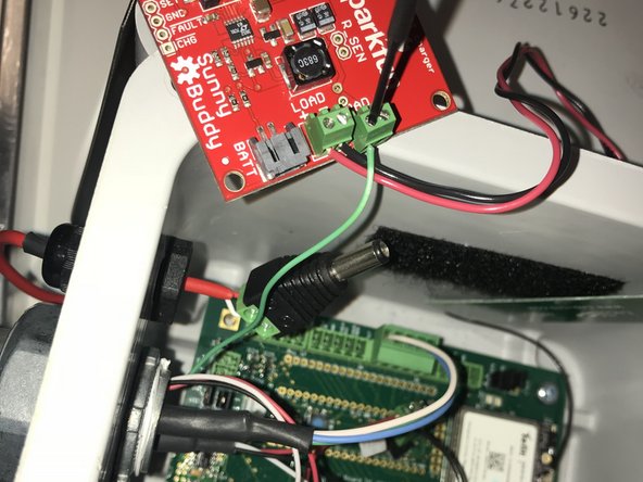
- Pull out the solar charger terminal from the board
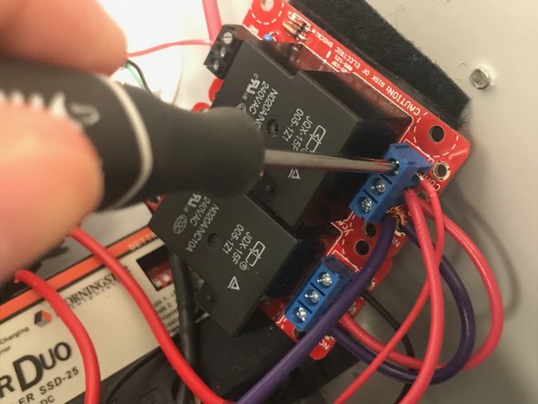
- Unscrew the green wire from the solar charger using the (small) flat head screwdriver
- Pull the module from the bottom; pulling the module in a different way may damage it
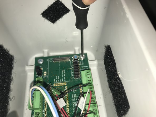
- Use the (small) Phillips screwdriver
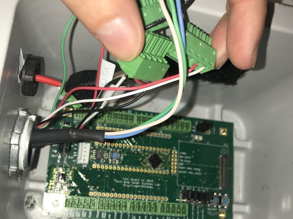
- For this step, we recommend you record the current location of the current wires/terminals or refer to our pin documentation for reassembly purposes
- Pin Documentation
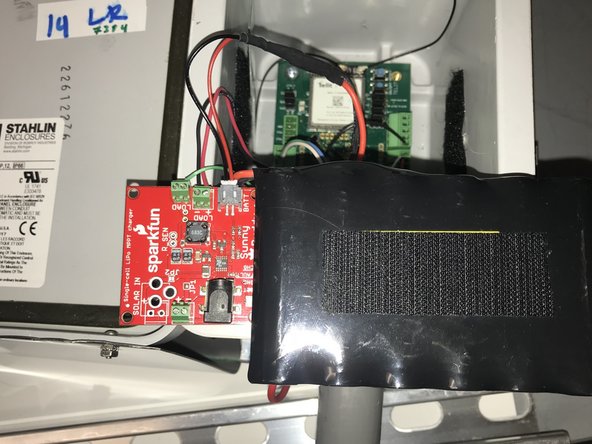
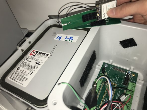
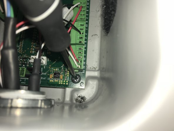
- We have provided a picture of the inside of the enclosure to depict what will still remain inside
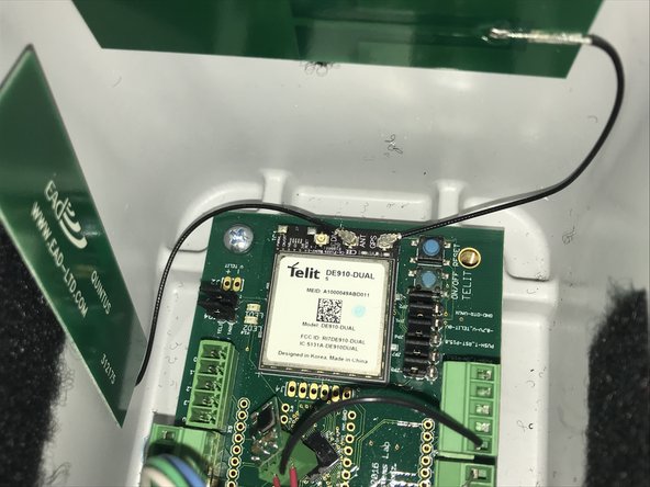
- With the interior of the small node removed, these are the components we should have (from left to right)
- Solar charger with an attached terminal
- Cell module with attached antenna on the "ANT" and "GPS" pins
- Board with the four screws
- The battery