Google Pixelbook Motherboard Replacement
ID: 103312
Description: In this guide, you will learn how to remove the...
Steps:
- Use the iFixit opening tools or a metal spudger to pry the rubber covers off the back of your Pixelbook.
- Peel the linings off completely until the back of the Pixelbook looks bare.
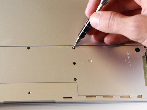
- Remove the two yellow 2.0mm screws by using a T3 Torx screwdriver.
- Remove the seventeen 3.0mm T5 Torx screws from the bottom panel.
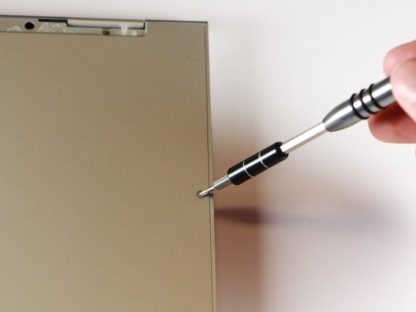
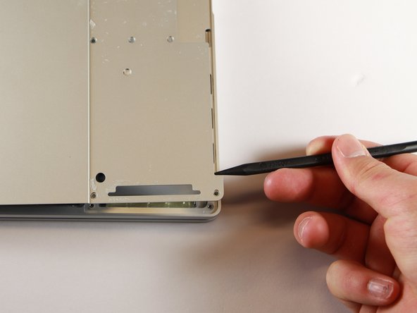
- Use the nylon spudger to pry the edge of the Pixelbook up until you can grab the edge with your fingers.
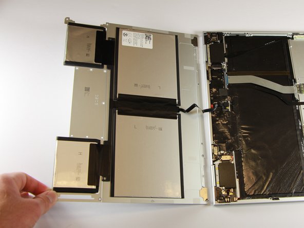
- Open the back panel completely and lay it flat so you see the whole inside of the computer.
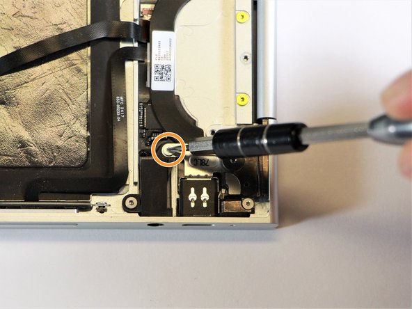
- Remove the yellow 2.0mm screw from the middle of the panel by using the T3 Torx screwdriver to turn the screw counterclockwise.
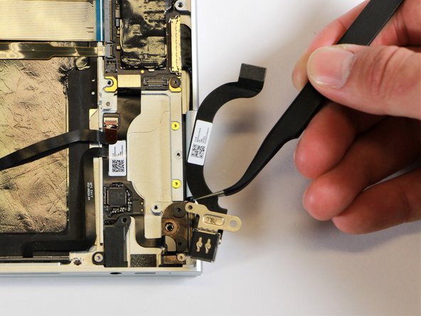
- Remove the small, black casing by using the spudger to lift it up from its place.
- Disconnect the flat, black cord from the main component by using a spudger to push it out of the slot, or by using your hand to carefully pull it out.
- Your back panel is now free from the main component.
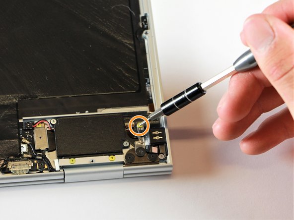
- Remove the two 3.0mm silver screws from the thin, black component by using a T3 Torx screwdriver to turn the screws counterclockwise.
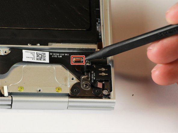
- Disconnect the thin, black and white cord from the motherboard by using the spudger to snap the connector up and out of place.
- Remove the thin, black component by pulling it up and out of the laptop with your fingers.
- This photo shows the bottom screw still in the black box, but yours should be removed.
- Remove the gold 2.0mm corner screw by turning it counterclockwise with a T3 Torx screwdriver.
- Using needle-nose tweezers, remove the silver casing by lifting it up and out of the computer.
- Remove the three 3.0mm black screws on the right side by using a T5 Torx screwdriver to turn the screws counterclockwise.
- Remove the silver 2.0mm screw on the left side by using a T3 Torx screwdriver to turn the screw counterclockwise.
- Disconnect the thin, black ribbon cable by using the spudger to lift it up from the computer.
- Use the needle-nose tweezers to remove the charging port by lifting the component up and out of the Pixelbook.
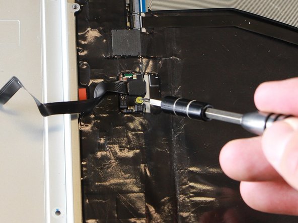
- Remove the three 2.0mm black screws from the sound card by using a T5 Torx screwdriver to turn them counterclockwise.
- Remove the gold 3.0mm screw by using a T3 Torx screwdriver to turn it counterclockwise.
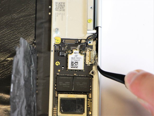
- Disconect the thin, black and red cord from the motherboard by using the spudger to snap the connector up and out of place.
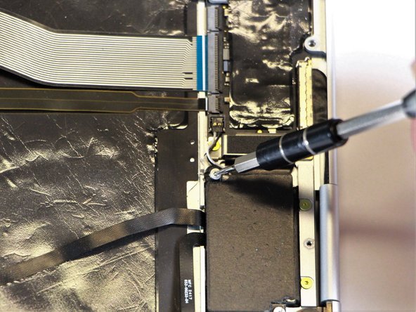
- Remove the yellow 2.0mm screw by using the T3 Torx screwdriver to turn the screw counterclockwise.
- Remove the small, red component by lifting it up with the spudger.
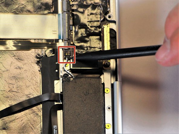
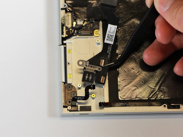
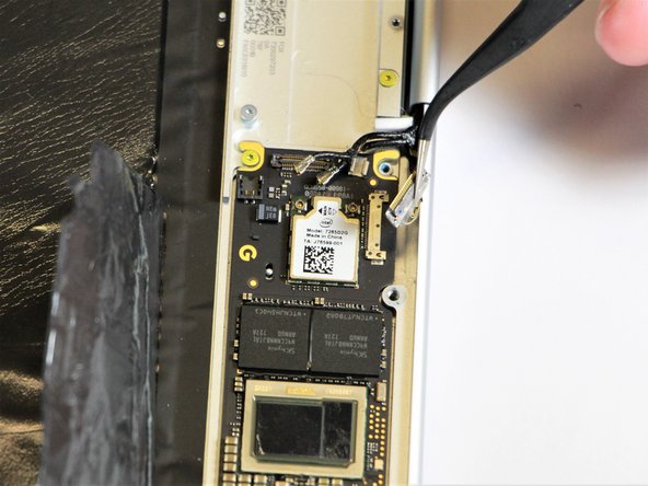
- Disconnect the metal component of the thin, black component by lifting it up with the spudger.
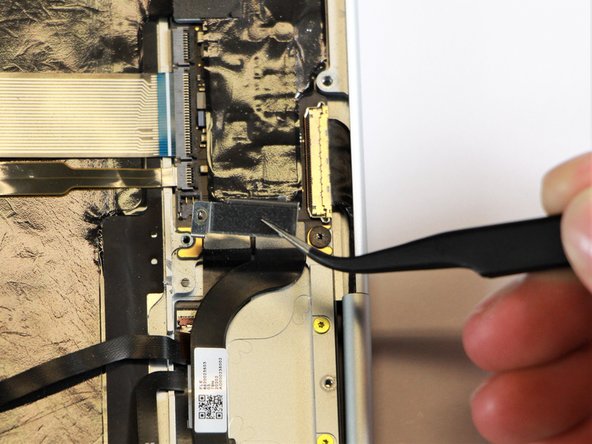
- Remove the right charging port by picking it up with the tweezers and lifting it from the computer.
- Disconnect the flat, black cord from the motherboard by using a spudger to push it upwards out of the slot, or by using your hand to carefully pull upward.
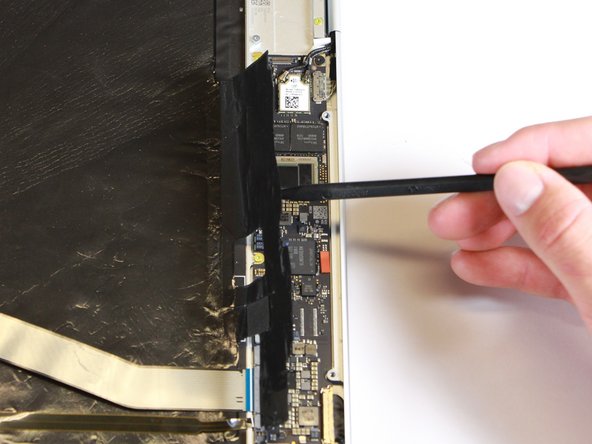
- Fold back the plastic covering on the motherboard using the nylon spudger.
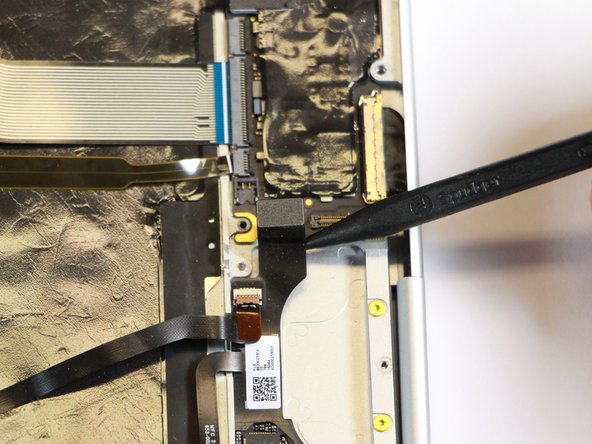
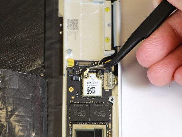
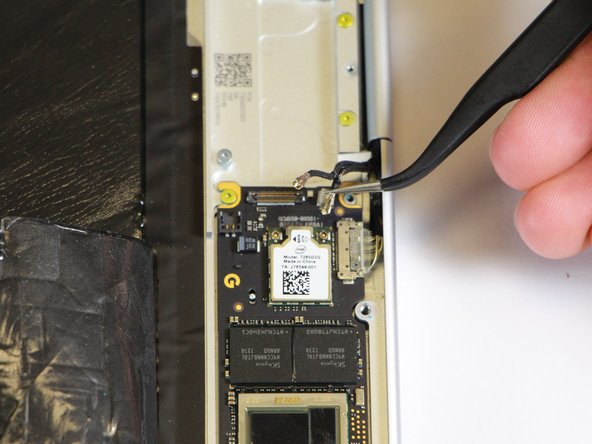
- Disconnect the two black cables from the motherboard by pulling the connectors upward using the needle-nose tweezers.
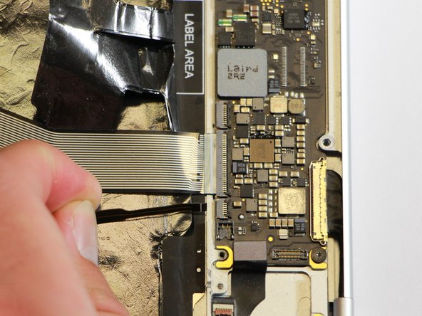
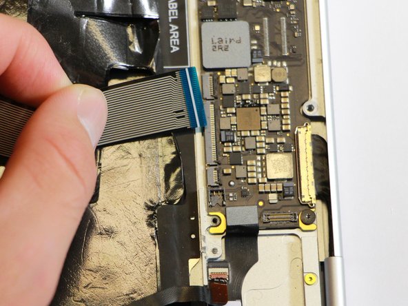
- Disconnect the flat ribbon cable from the motherboard by using your hand to gently pull it out of the socket, or by using a pair of tweezers to pull it out.
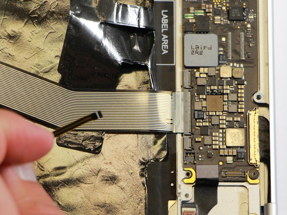
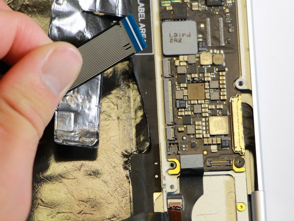
- Disconnect the large flat ribbon cable from the motherboard by using your hand to gently pull it out of the socket, or by using a pair of tweezers to pull it out.
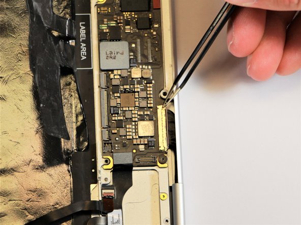
- Raise the retaining latch of the motherboard connector by using the needle-nose tweezers.
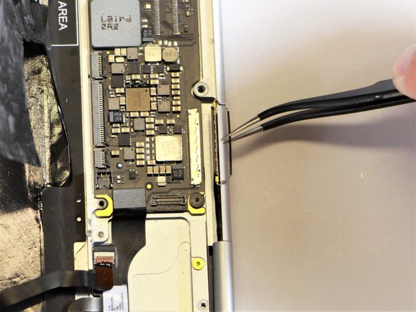
- Disconnect the large flat cable from the motherboard by gently pulling on the latch using the needle-nose tweezers.
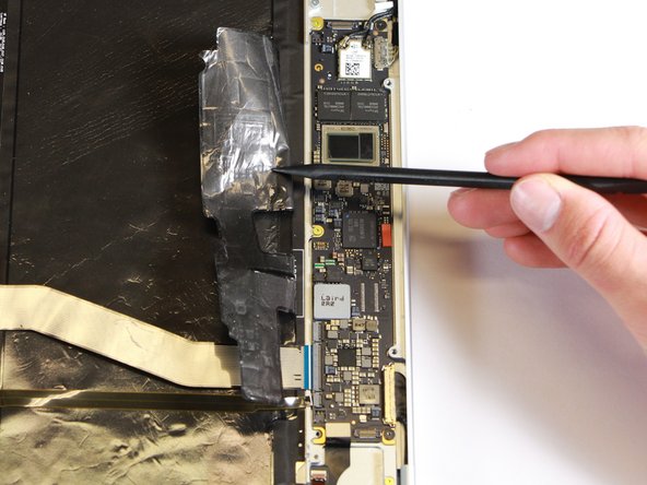
- Disconnect the flat cable from the motherboard by using the needle-nose tweezers to gently pull the connector out of the slot.
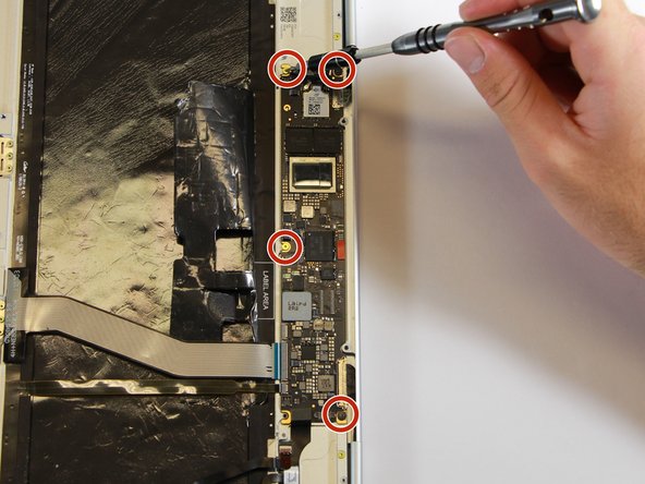
- Remove the gold 3.0mm screws and the black, flat 2.0mm screws from the motherboard by using a T3 Torx screwdriver to turn the screws counterclockwise.
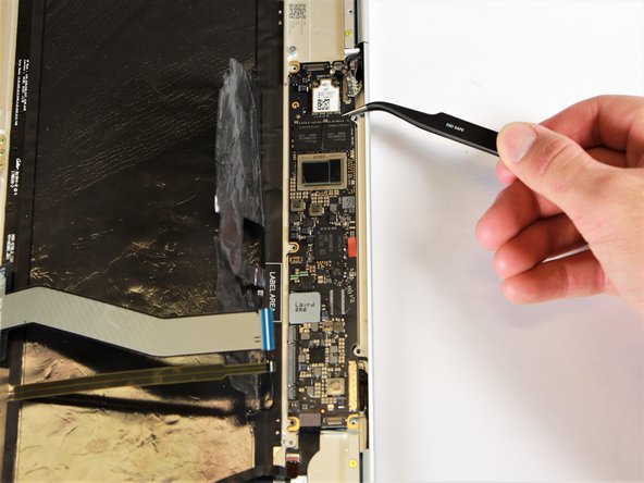
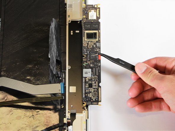
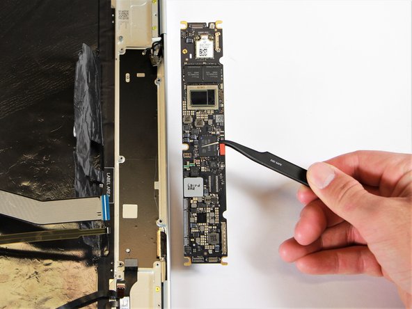
- Remove the motherboard by gently lifting it out of the laptop using the needle-nose tweezers.