Motorola Moto Z2 Play Rear Facing Camera Replacement
ID: 103363
Description: Use this guide to replace the rear-facing...
Steps:
- Insert a SIM eject tool, bit, or a straightened paperclip into the hole in the SIM tray, located at the top left edge of the phone.
- Double-check to make sure that you are not mistakenly inserting the tool into the microphone hole.
- Push firmly to eject the tray.
- Pull the tray straight out to remove the tray.
- Power off your phone before you complete any replacement steps.
- Heat the edges of your Motorola Moto Z2 Play screen for two to three minutes with a heat gun. You adjust the heat gun to 85 degrees centigrade, and be careful not to hold the heat gun on one position for too long; to avoid damaging, or "hotspotting" the LCD. The screen should be very warm, but not painful, to the touch. Reheat as necessary.
- If screen is cracked put strong adhesive tape across the screen in order to avoid breaking the screen further and receiving cuts.
- If you don’t have access to a heat gun, a hair dryer can be used.
- Place suction cup in the middle of the screen and press down.
- Pry the screen by wedging the plastic opening tool under the screen at the charging port.
- Work your way around the screen with the plastic opening tool.
- When you pry near the top-right and bottom-right corners, be careful not to pry too far, or you risk damaging the display cable.
- Complete these steps carefully because the screen is delicate and can easily crack. If the screen begins to resist prying, reheat the adhesive with your heat gun.
- Use a suction cup to lift up screen from left to right.
- If you don’t have a suction cup, wedge a spudger or a small plastic card under the screen and lift slowly.
- Failure to lift screen from left to right can cause damage to interior wires of your phone.
- Identify ribbon connector at the top right of the phone.
- Pry the black locking bar up gently with a plastic opening tool.
- Remove the ribbon wires by pulling them out of the connector with a tweezer.
- The locking bar is the small black bar located on the digitizer’s ZIF connector.
- Be sure to push the locking bar back down using a spudger after you put the ribbon wire back in since the lock does not lock automatically.
- Identify the ribbon cable, located at the bottom right of the phone.
- If present, remove kapton (orange) tape covering the cable connector.
- Flip up the small locking flap on the ZIF connector and use tweezers to slide the cable straight out of its socket.
- Excessive force is not needed.
- Lift the screen from the phone to completely detach.
- If screen doesn't detach, go back to step 7 and 8 to make sure the bar is unlocked and ribbon connector is fully detached.
- During reassembly, you may need to apply or replace the display adhesive on your display assembly. Use our display adhesive application guide to apply the adhesive and reseal your device.
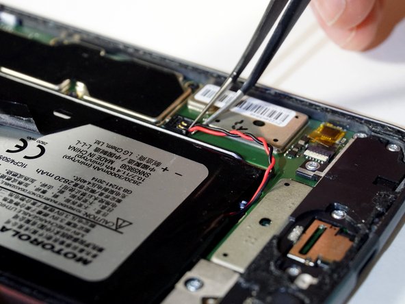
- Remove the orange tape, located at the bottom right of the phone, using tweezers.
- Do not discard tape.
- Detach the red and black battery wire by lifting up with tweezers.
- Peel back the black tape that is located on the battery.
- Make sure you pull back gently so you can reuse the tape with reassembly.
- Lift the black tape and slide a card under the battery.
- Align the card parallel and under the battery.
- Wedge the card further under the battery.
- Lift the card up to assist in removing the battery from the adhesive.
- Lift to remove the battery from the device completely.
- Remove the three silver 2.6 mm T3 Torx screws on the speaker shell at the top of the phone with a screwdriver by turning counterclockwise.
- Remove the four black 3.5 mm T3 Torx screws on the speaker shell at the top of the phone with a screwdriver by turning counterclockwise.
- It is helpful to keep screws on a magnetic surface to avoid losing them.
- Lift up the silver metallic tape using the tweezers.
- Lift gently to completely remove speaker housing using tweezers.
- Try lifting the speaker housing from both sides slightly before removing completely.
- Place the housing upside down in order to continue working.
- Pry the speaker from the housing with a plastic opening tool.
- When reassembling, make sure the metal connectors of speaker are in the bottom left and right corners (correct orientation).
- Speaker clicks in on reassembly.
- Remove the seven silver 2.6 mm T3 Torx screws on the black battery cable cover at the bottom of the phone with a screwdriver by turning counterclockwise.
- Remove the single black 3.5 mm T3 Torx screw on the black battery cable cover at the bottom of the phone with a screwdriver by turning counterclockwise.
- It is helpful to keep screws on a magnetic surface to avoid losing them.
- Lift the battery cover with tweezers starting on the right side slightly to dislodge the cover.
- Lift the battery cover with tweezers from the left side slightly to dislodge the cover.
- Remove the battery cover with tweezers by solidly gripping the left side of the cover and lifting up.
- Tilt the front of the black audio jack up with tweezers.
- Lift the audio jack out of its housing with tweezers.
- Little force is required to remove the audio jack.
- Remove the three black 2.6 mm T3 Torx screws on the motherboard panel at the side of the phone with a screwdriver by turning counterclockwise.
- Place a plastic opening tool under the edge of the motherboard.
- Lift the motherboard from the right edge like a book towards the left.
- Identify the connector on the top left of the device.
- Detach the connection on the bottom of the motherboard.
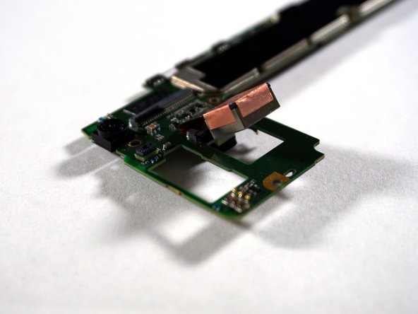
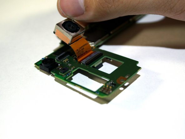
- Flip over the motherboard so the rear-facing camera and its ribbon can be seen.
- Bend the camera back to reveal its ribbon-wire port.
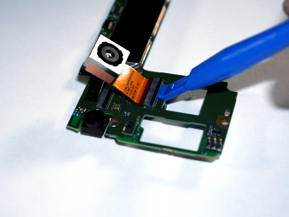
- Lift the locking bar on the ZIF connector that is under the rear facing camera with a plastic opening tool.
- You can also use a spudger to complete this step.
- Pull out the ribbon connector for the rear-facing camera.