Motorola Moto X4 Motherboard Replacement
ID: 103404
Description: Follow this guide to remove the motherboard on...
Steps:
- Insert a SIM card eject tool, bit, or a straightened paperclip into the small hole in the SIM card tray, located at the top left edge of the phone.
- Press to eject the tray.
- Remove the tray from the phone.
- Before you begin, turn off your phone.
- Heat an iOpener and apply it to the left edge of the phone for two minutes.
- You may need to reheat and reapply the iOpener several times to get the phone warm enough. Follow the iOpener instructions to avoid overheating.
- A hair dryer, heat gun, or hot plate may also be used, but be careful not to overheat the phone—the display and internal battery are both susceptible to heat damage.
- As you wait, take note of the the following areas:
- Display cable—be careful not to slice too deeply near the edge here, or you may damage the display cable.
- Fingerprint sensor cable—be careful not to slice too deeply near the edge here, or you may damage the fingerprint sensor cable.
- Apply a suction cup to the screen, as close to the heated edge as possible.
- Pull on the suction cup with strong, steady force to create a gap in the seam.
- Insert the point of an opening pick into the gap.
- Depending on the age of your phone, this may be difficult. If you are having trouble, apply heat to the edge and try again.
- Slide the opening pick along the edge to slice through the adhesive.
- Leave an opening pick in the seam to prevent the adhesive from re-sealing.
- Heat the top edge of the phone with an iOpener.
- Carefully slice around the corner and through the top edge to separate the adhesive.
- Heat the screen's right edge with an iOpener.
- Be careful not to slice too deeply near the cables to avoid damaging them.
- Use an opening pick to slice along the right edge to separate the adhesive.
- Repeat the previous steps to heat and slice the bottom edge of the phone.
- Do not try to remove the screen yet—it is still attached to the phone by delicate flex cables.
- Carefully lift up the left edge of the screen and cut away remaining adhesives with an opening pick.
- Swing open the screen and prop it up with a small box as you work on disconnecting the flex cables.
- During reassembly, this is a good time to power on your phone and test all functions before sealing it up. Be sure to power your phone back down completely before you continue working.
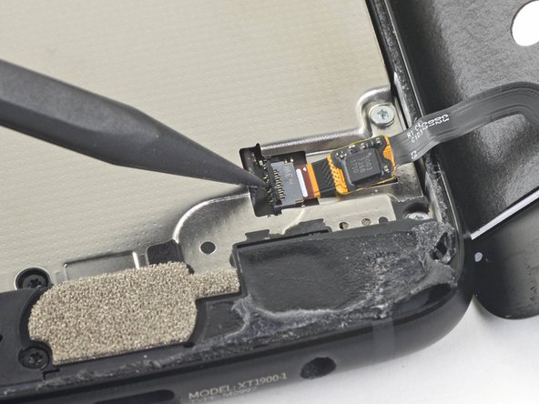
- Slide the point of a spudger underneath the fingerprint sensor cable and gently pry up to loosen the cable from the phone.
- Do not pull on the cable. It is still attached to the phone by a delicate ZIF socket.
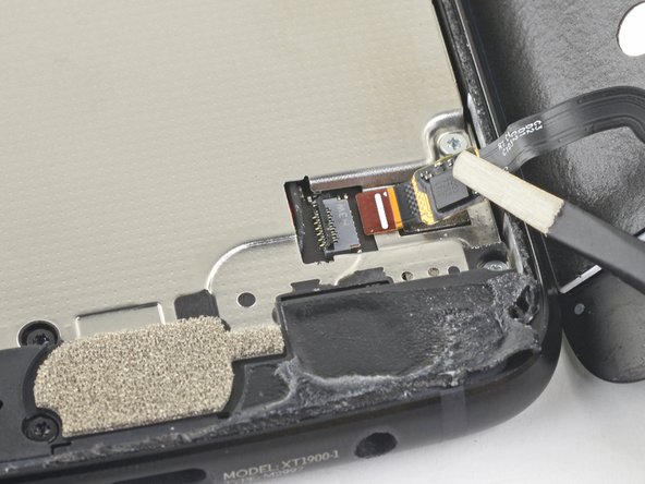
- Use the point of a spudger to flip up the lock bar on the fingerprint sensor's ZIF socket, near the bottom right of the phone.
- Use tweezers to carefully slide the fingerprint sensor cable out of the socket.
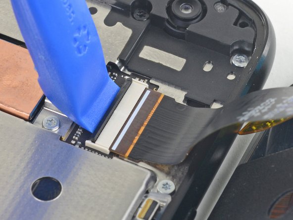
- Use an opening tool to flip up the wide lock bar on the display cable's ZIF socket, near the top right of the phone.
- Use tweezers to carefully slide the display cable out of the ZIF socket.
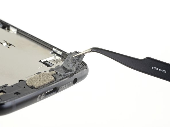
- Remove the screen.
- During reassembly, follow this guide to clean the existing adhesive off and install custom-cut adhesives for your phone.
- Remove the following twenty screws securing the midframe:
- Eleven silver 2.7 mm-long T3 screws
- Nine black 3.6 mm-long T4 screws
- The midframe is still held in place by clips.
- The next few steps show how to loosen the midframe clips.
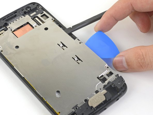
- Insert the flat end of a spudger under the right edge of the metal midframe and pry up to loosen the midframe.
- Insert an opening pick in the edge to hold the midframe in place.
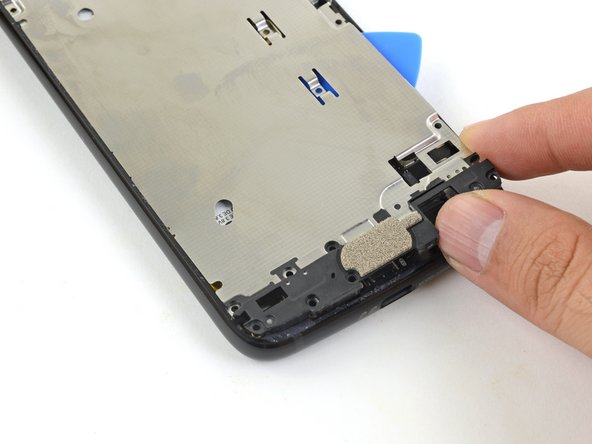
- Insert the flat end of a spudger under the lower right edge of the midframe and pry up to release the midframe clip.
- Grasp the lower edge of the midframe and pull the edge slightly to the right, to clear the metal midframe clip.
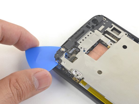
- Insert the point of an opening pick under the top left corner of the midframe and twist slightly to release the top clip.
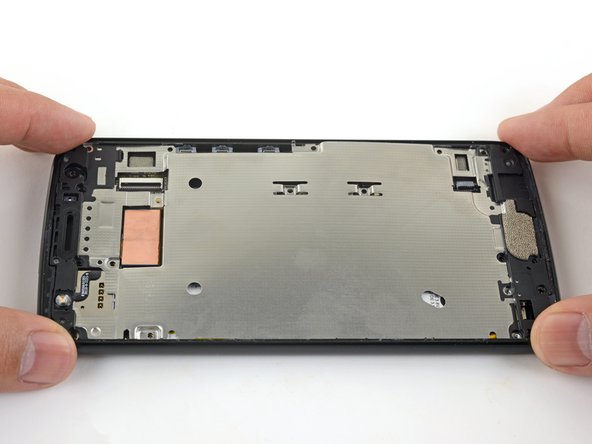
- Remove the midframe.
- To reinstall the midframe:
- Align the the midframe's top edge to the phone and press it into position.
- Shift the bottom edge slightly to the left, to maneuver the left metal midframe clip underneath the phone edge.
- Press the midframe's bottom edge into position.
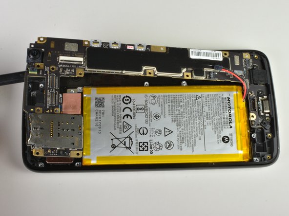
- Insert the point of a spudger underneath the top edge of the battery connector.
- Be careful not to dislodge the small surface-mounted components surrounding the socket.
- Gently pry up the connector to disconnect the battery.
- To re-connect the battery, align the connector on top of the socket, and press it down with your finger or a spudger.
- Remove the T3 screw that is holding in the motherboard.
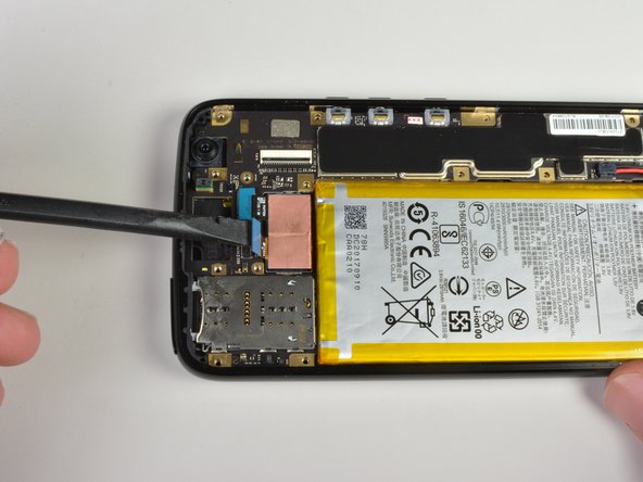
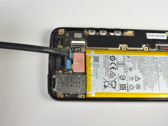
- Use flat edge of the spudger to pry up the two blue connectors near the top of the device.
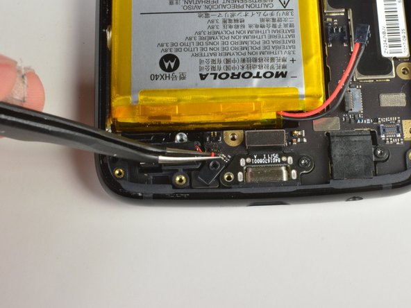
- Use flat side of spudger to pry up connector near the bottom of the device.
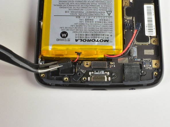
- Using a pair of tweezers disconnect the vibrating motors connector near the bottom of the device.
- Caution: these wires are very delicate!
- Also note that while it may not look the same, this connector also lifts up, similar to the camera and battery connectors, and does not slide out.
- Alternatively, you can also leave the connector plugged in and simply remove the vibration motor from the frame and keep it together with the motherboard as you remove it, being careful to not dangle it from the small wires.
- Carefully pry up the motherboard using the spudger.
- The previously disconnected wires may have to be held back in order to easily remove the motherboard.