Rockford Fosgate P300-12 Teardown UPDATE FEB 2025
ID: 105231
Description:
Steps:
- Front view
- Remove the 8 coarse thread wood screws and gently pry the plate out
- Carefully remove the 3 knobs and the 1 screw between the 2 10A fuses. then the plastic face should pop off
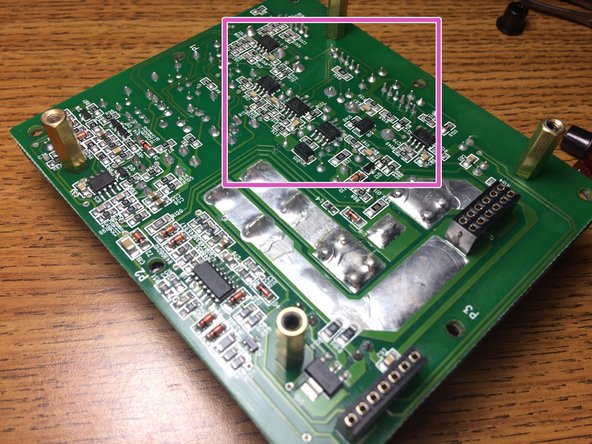
- Crossover / Gain
- Power Supply and output FET's
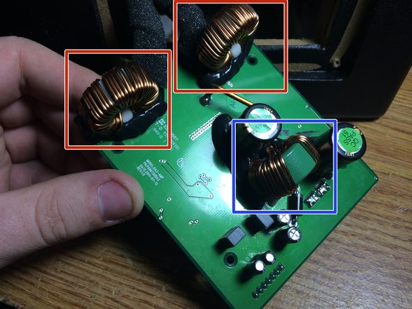
- Power Supply Transformer
- Output Filters
- The 2 boards are held together by 4 screws on the edges of the PCB, gently pull them apart, they will only be held together by pin headers. Here you can see the 2 output filters and the power supply step up transformer
- The board with the FEMALE pin headers is the front board with the plugs on it. the crossover network consists of JRC 4850's
- There are 4 of these "GA7E1S" FET's that i cant find any info on. i would assume by looking at the boards that 2 are the power supply and the other 2 are the outputs
- There are NO heatsinks anywhere in this unit which i find amazing. but the FETS most likely use the massive copper planes on the board as the heatsink
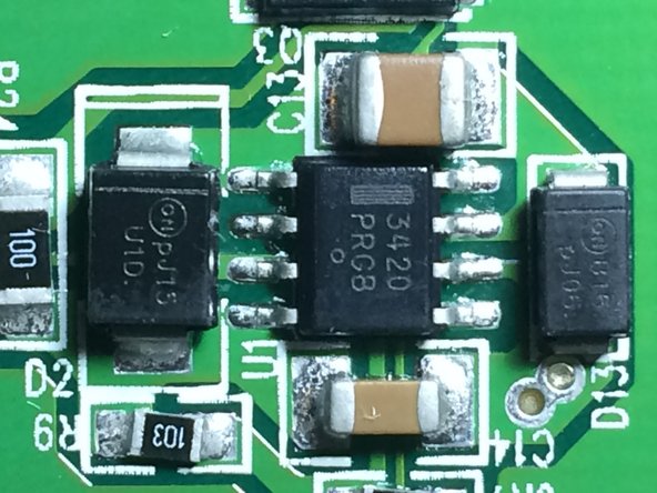
- More jelly bean logic around the board
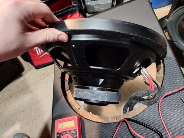
- The custom 12" driver. it appears to be a DVC driver, but its just a SVC with 2 pairs of leads going to it
- Here's my February 2025 update. i Finally have pulled this P300-12 again to do what i have been requested a few times, and that is to pull the actual driver itself
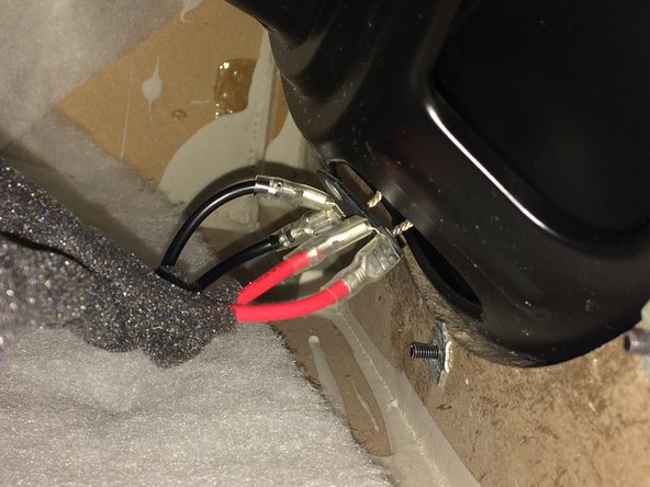
- Once you remove the 8 3MM hex head bolts the driver is not glued in but it does fit very snug with the textured vinyl covering making it very difficult to remove from the front. It was MUCH easier to pop out from the back sticking my hand through the amplifier hole.
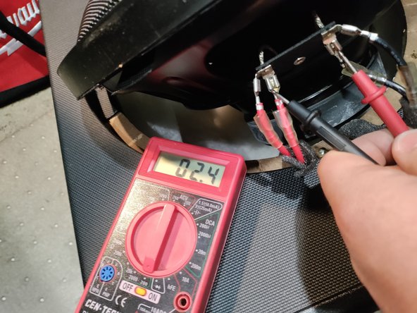
- Here we again see the twin pair of leads going to the SVC driver, they really do NOT want you to remove this thing, each spade terminal is soldered onto the driver!
- And the answer to the comments, the Rockford Fosgate P300-12's possibly custom spun driver is 2 Ohms