Toshiba Satellite L855-S5119 Charger Port Replacement
ID: 105287
Description: This guide will help you gain access to and...
Steps:
- Turn the laptop face down to expose the back.
- Locate the battery.
- Locate the battery latches. The battery latch mechanism can be compared to a door -- The right latch, when pushed right, unlocks the battery, while the left latch, when pushed left, releases the battery, pushing it out from its container.
- Push the latch on the right to the right to unlock the battery latch locking mechanism.
- Push the battery latch on the left to the left to unlock the battery.
- With the left battery latch pushed left, remove the battery from its port by lifting the battery from the middle of the battery.
- The battery will come free.
- Turn the laptop over to place it top down.
- Use a Phillips #1 screwdriver to remove the screw holding in the back plate. This screw does not come out of the plate.
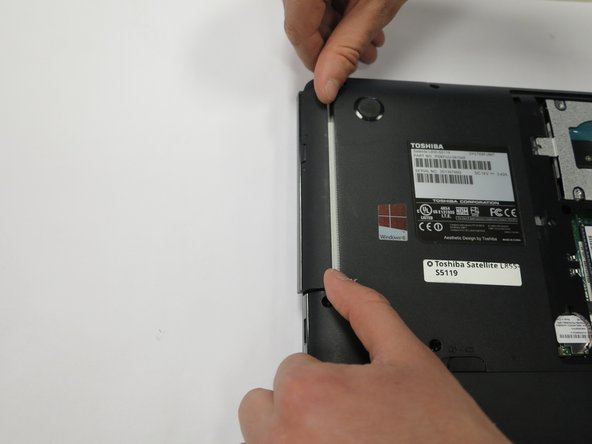
- Lift the back plate off the laptop, exposing the RAM and Hard Disk.
- Using a Phillips #0 screwdriver, remove the single 3mm screw.
- Rotate the laptop so that you have access to the optical drive.
- The optical drive is now only attached by a port in the drive's back. The optical drive can be pulled straight out of its housing.
- Remove the drive.
- Unscrew the hard drive.
- There could be up to five 3mm screws - One on each corner of the hard drive, and one at one end of the hard drive, attaching the drive to the laptop's frame.
- Carefully push the hard drive away from its port. This should not require substantial force.
- Lift the hard drive out.
- Some hard drives have a plastic tab, which can be lifted from to remove the hard drive.
- Otherwise, take hold of opposite sides of the hard drive and lift the drive straight up.
- Unscrew the screws circled in red. This includes eleven 6mm screws, and one 5mm screw underneath where the optical drive was housed. All screws can be removed with a Phillips #0 screwdriver.
- Carefully remove the back cover. The battery holder contains notches that help hold the case in place, so take care not to break those.
- Locate the DC power port. Note the 4-pin connector attaching the port to the motherboard.
- Remove the 4 pin female connector from the male connector attached to the motherboard.
- Lift the DC power port from the bracket holding it in place.
- There are black plastic housings for the wires, holding the wires in position. Remove the red and black wires connecting the DC Port to the 4-pin power connector from underneath the black plastic housings.
- Remove the DC Power port and 4 pin connector.