HP Elitebook 820 G1 Monitor Display Replacement
ID: 106645
Description: Displays can get easily damaged either with...
Steps:
- Ensure the laptop is completely powered off and power adapter is unplugged before removing the battery.
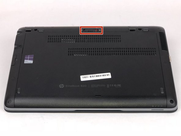
- Turn over laptop so that the bottom is showing.
- Unlock the latch.
- Remove the back cover and you will then be able to see the battery.
- Unlatch the two latches securing the battery in the case.
- Use a plastic opening tool to lift and remove the battery.
- Remove the hard drive by unscrewing the four 8mm screws with the T7 philip's head.
- Pry off ten rubber paddings on the outer edge of the laptop to reveal the torx screws.
- Unscrew the ten 8mm torx screws that are under the rubber paddings using the T7 tip torx screwdriver.
- Remove the two 4mm screws indicated by the M2.5X4 using the J00 tip screwdriver.
- Remove SD card cap by just sliding out to reveal one screw.
- Remove the two 3mm screws indicated by the M2.03 using the J00 tip screwdriver.
- Remove the 4mm SD card screw using the J00 tip.
- Remove the one 4mm fan screw using the J00 tip screwdriver.
- Remove screw and metal plate to expose ribbon cable connector.
- Use an opening tool to pry up the ribbon connector to disconnect.
- Turn laptop over back to normal position as shown in the image.
- Use opening tools to pry up keyboard.
- When prying up keyboard, be sure to start near any corner of the keyboard.
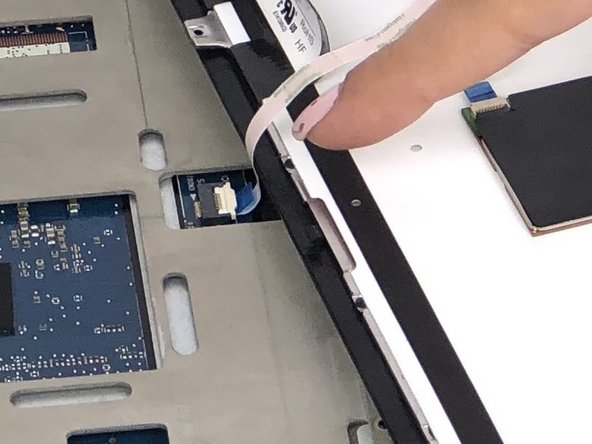
- There are two ribbon cables that must be disconnected before fully removing keyboard.
- Carefully lift keyboard on one side to expose the two ribbon cables.
- Use an opening tool to lift up the locking clip and unplug the two ribbon cables.
- Remove the two 4mm screws centered notated by the keyboard logo using the J00 tip.
- Once keyboard has been fully removed, the system case containing the motherboard can be lifted out easily.
- The display is connected to the shell of the laptop.
- Unplug fan cable by pulling away from its connector.
- Unscrew the two 6mm fan screws using the J00 tip.
- Fan screws are encased in springs and cannot be removed.
- Retrieve the monitor display connected to the plastic chassis.
- Unscrew the two 4mm hinge screws using the Philips 00 tip screwdriver.
- Unhinge the monitor display from the chassis.