PowerRay Camera Module Replacement
ID: 106661
Description:
Steps:
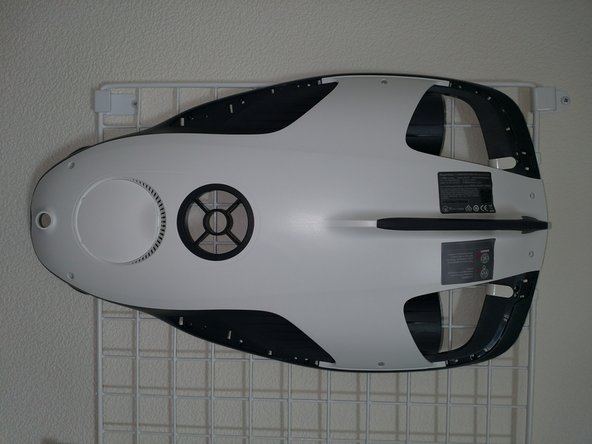
- Remove the four protective parts on the back of the unit.
- Check the position of the claws and be careful not to break any parts.
- Remove all the following screws:
- Red M2.5×6 (16 pieces)
- 青 M2×5 (2本)
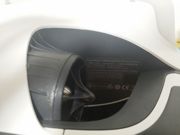
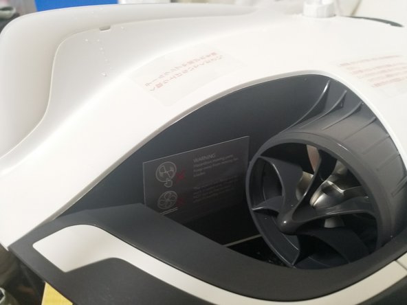
- Remove the warning label and S/N label.
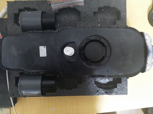
- Remove the bottom exterior
- Remove all screws that secure the airtight module to the housing
- Red M2.5×12 (8 pieces)
- Blue M2 x 5 (4 pieces)
- Remove all screws from the airtight module
- M2.5x8 (48 pieces)
- Be careful not to cut the cables when removing the upper housing.
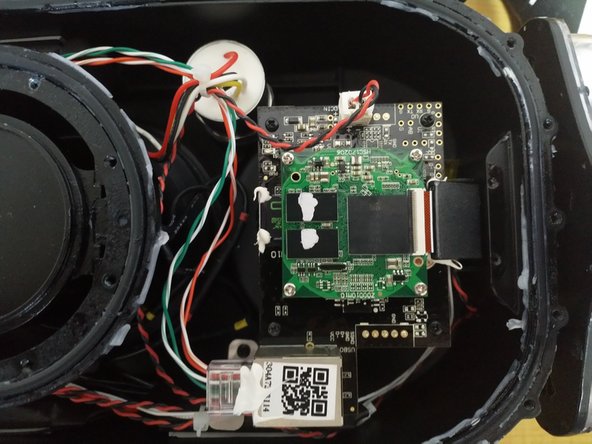
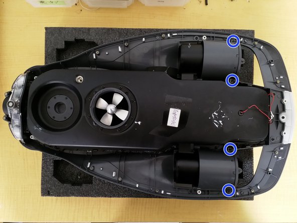
- Remove all the screws that attach the camera module
- M2x5 (8 Pieces)
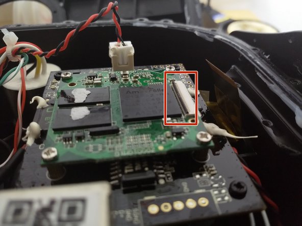
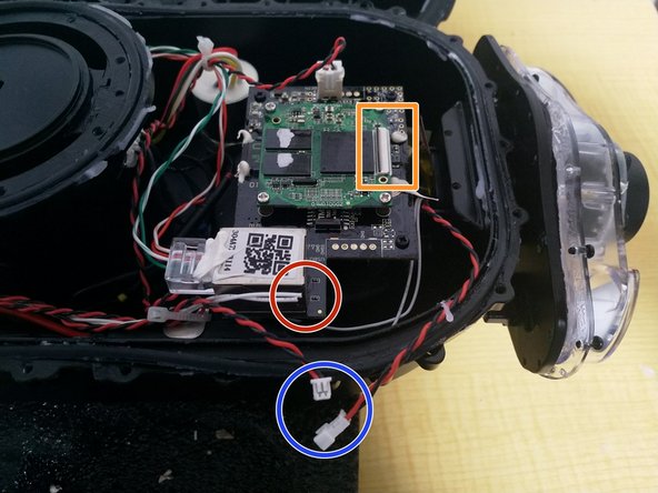
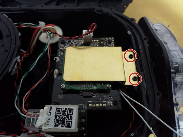
- Remove the screws circled in red. M2×5 (2 pieces)
- Remove the heatsink indicated by the orange arrow.
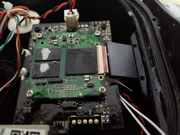
- Unlock the flexible cable connector (raise the black lock)
- Pull the flexible cable straight out.
- The ferrite core indicated by the orange arrow will be reused, so keep it.
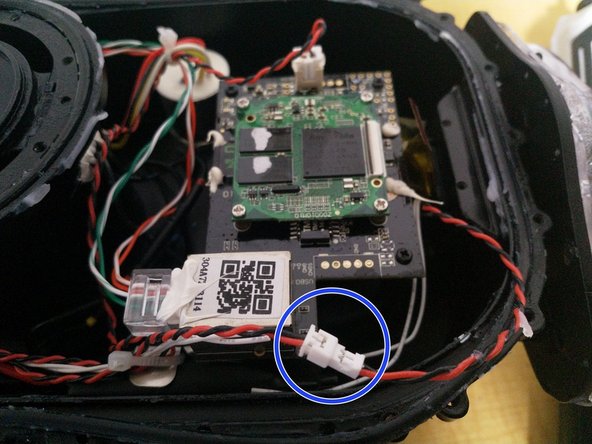
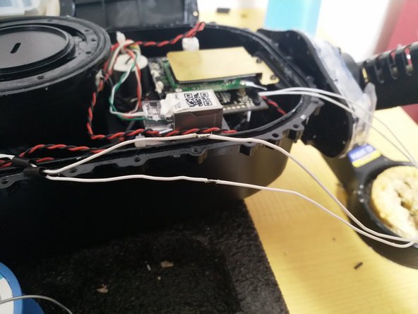
- Cut the white magnet cable (red circle position)
- Remove the LED connector (blue circle position)
- After confirming that the flexible cable, magnet cable, and LED cable have been removed, pull out the camera module.
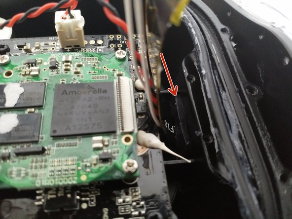
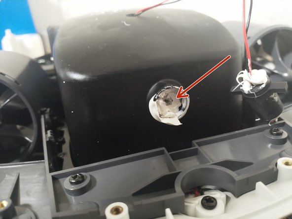
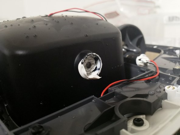
- Modules that have been waterproofed with sealant at the position indicated by the arrow, are defective products from the initial lot and must be replaced.
- Insert the camera cable into the main unit from the arrow position (flexible cable, magnet cable, LED cable)
- Check that the O-ring is not scratched, cut, or damaged, apply grease to it and fit it firmly into the groove.
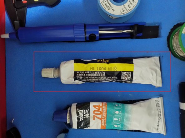
- Attach the silicone cover at the arrow position.
- Be careful when using tweezers not to damage the cable.
- Attach the camera module to the mount
- Tighten diagonally a little at a time, tightening to a torque of 4.9 [cN・m].
- Finally, tighten it one more time at 4.9 [cN・m]
- Be careful not to pinch the O-ring or any debris when fixing.
- Connect the LED cable connector
- Insert the ferrite core that you removed earlier.
- Remove the Kapton tape from the end of the cable.
- Install the flexible cable
- Be careful not to touch the terminals after removing the Kapton tape.
- When fastening the connector tabs, make sure the cables are inserted parallel to each other.
- Replace the double-sided tape on the back of the heat sink
- Remove the release paper from the double-sided tape and secure it with M2 x 5 (2 pieces).
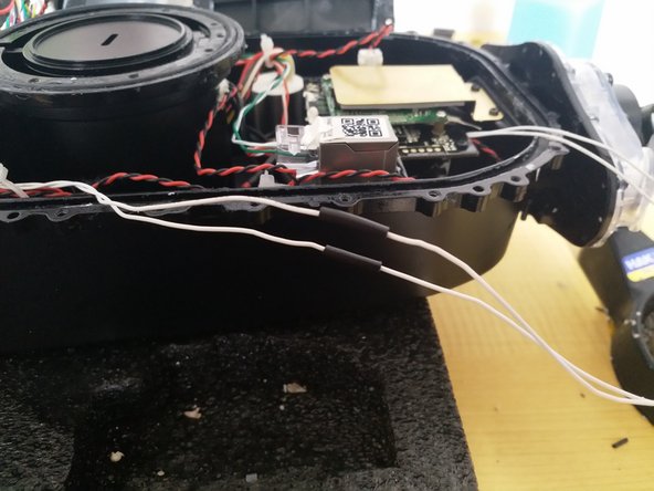
- Peel off the coating of the magnetic cable on the main unit and insert the shrink tube.
- Solder the cable on the main unit and the cable on the camera.
- Fix the shrink tube with a heat gun
- The LED lights up just like in the picture.
- Startup sound is normal
- All motors and cameras are functioning normally.
- Check that both O-rings are free of scratches, damage, and dirt, and apply grease to them and align them with the grooves.
- Close the upper module, being careful not to catch any cables or debris.
- Place the plate on and tighten all 48 screws
- M2.5 x 8 (48 pieces)
- Tightening torque = 39 [cN・m]
- When tightening, always tighten diagonally
- Install the M2.5 x 12 (8) screws.
- Insert translation here
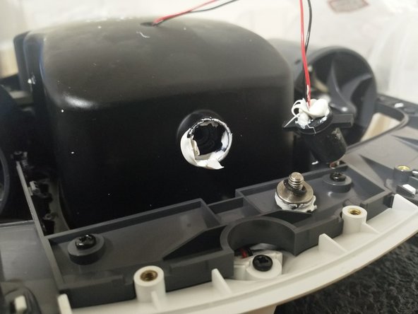
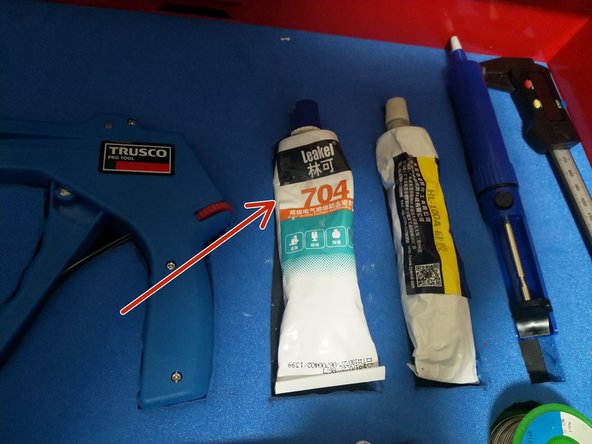
- Remove the silicone sealant
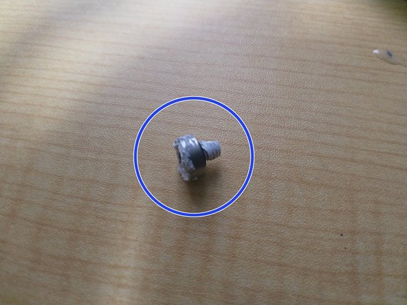
- Remove the airtight bolt with a 3mm hexagonal wrench
- Install the airtight test bolt in the place where the airtight bolt was removed.
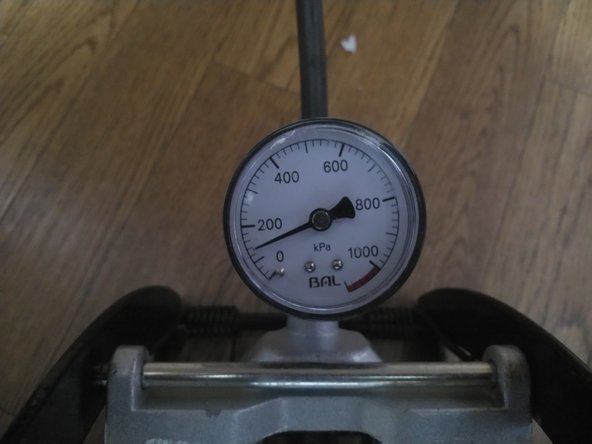
- Attach the hose and pump to the airtight test bolt
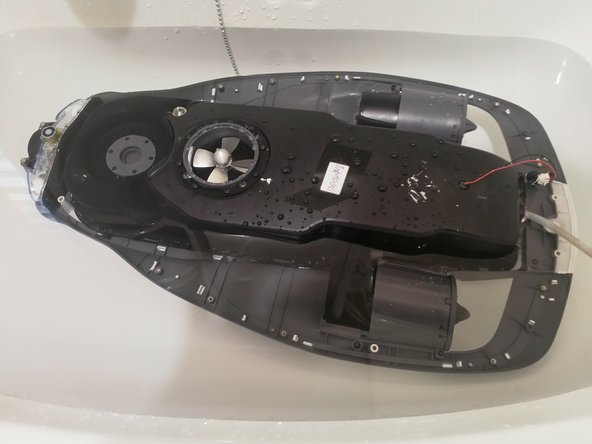
- Pressurize to 140kPa, submerge in water, and check for no leaks for 3 minutes.
- Remove the airtight test bolt
- Wrap the O-ring and sealing tape around the airtight bolt that you just removed and install it.
- Seal the installed airtight bolts with sealant.
- Attach M2.5 x 6 (14 pieces)
- Attach M2×5 (2 pieces)
- Attach the four exterior parts
- Attach the safety seal and S/N seal