HP 15-R263DX RAM Replacement
ID: 106681
Description: If the computer won't load past the startup...
Steps:
- Eject the battery from the computer by sliding the two clips on the bottom of the computer toward the center of the computer.
- Slide the battery out as shown in the picture.
- Using a Phillips #1 screwdriver, remove the small screw next to the disc engraving shown in the picture.
- Gently slide the optical drive out of the side of the computer.
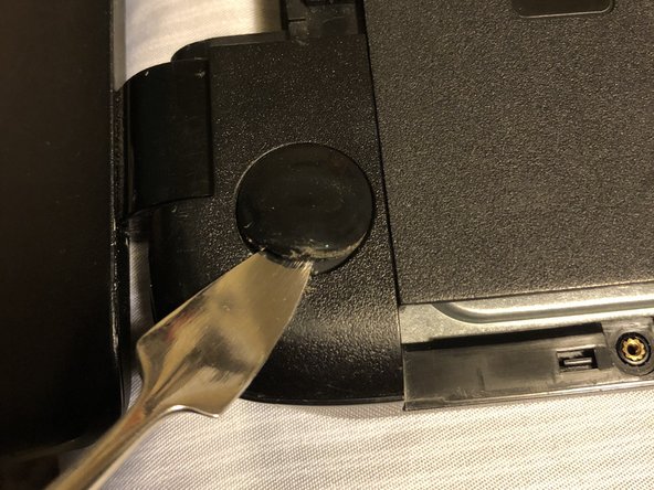
- Locate the two corner grips on the hinge side of the computer.
- Using a metal spudger, remove the two corner grips to reveal the screws.
- Remove the 11 small screws on the bottom of the computer that are shown in the picture.
- Remove the 2 small screws that are on the bottom side of the disc tray slot.
- These screws are shorter and wider than the others.
- Once the keyboard is loose, do not immediately pull away from computer. It is attached by the ribbon connector.
- Using a spudger, pry around the edges of the keyboard until all clips are disengaged and the keyboard is loose from the computer.
- To disconnect the ribbon connector, flip up the black clip shown in the picture.
- Gently pull the ribbon until disconnected.
- Disconnect the other two ribbon connectors underneath the keyboard by fliping up the black clips.
- Remove the 4 small screws shown in the picture.
- Disengage the face plate clips by prying the case away from around the outer edge of the face plate with a metal wedge.
- The face plate can then be lifted away from the computer.
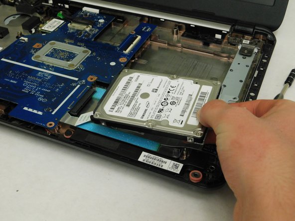
- Remove the 2 black screws holding the hard drive to the computer frame.
- Gently slide the hard drive away from the motherboard to disconnect it.
- After it's disconnected, lift the hard drive up to remove it from the computer.
- Remove the 2 screws holding the motherboard into the case of the laptop.
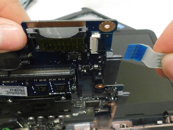
- Remove the connections around the motherboard.
- There is a connection hidden underneath the board. Remove this one last as you will need to lift the motherboard up to access it.
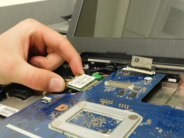
- Remove the screw holding the WiFi chip in place.
- Slide the chip away from the motherboard and set it elsewhere inside the computer.
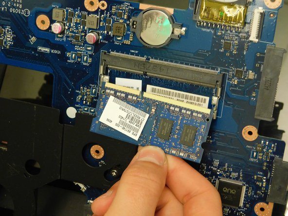
- Flip the motherboard over to access the underside revealing the RAM.
- Remove the RAM chip by simultaneously prying the 2 spring clips away from the RAM.
- The RAM will pop up when both clips are completely released.