Dell Inspiron 11 3179 Display Assembly Replacement
ID: 106702
Description: In this guide, we will show you how to remove...
Steps:
- WARNING: Before working inside your computer, read the safety information that shipped with your computer and follow the steps in Before working inside your computer. After working inside your computer, follow the instructions in After working inside your computer.
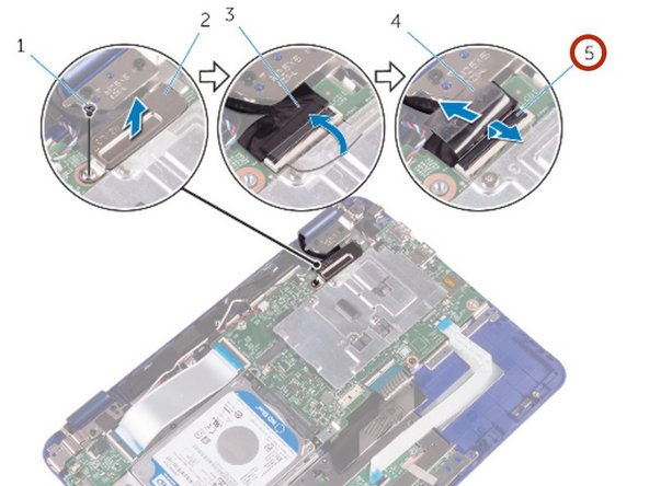
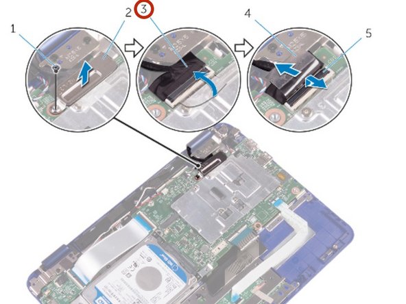
- Remove the screw that secures the display-cable bracket to the system board.
- Lift the display-cable bracket off the system board.
- Peel off the tape to access the display cable.
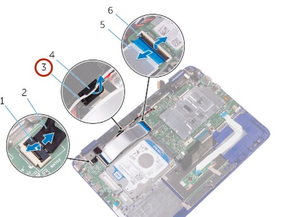
- Open the latch and disconnect the display cable.
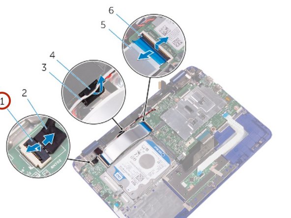
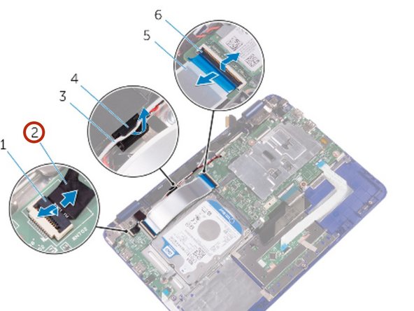
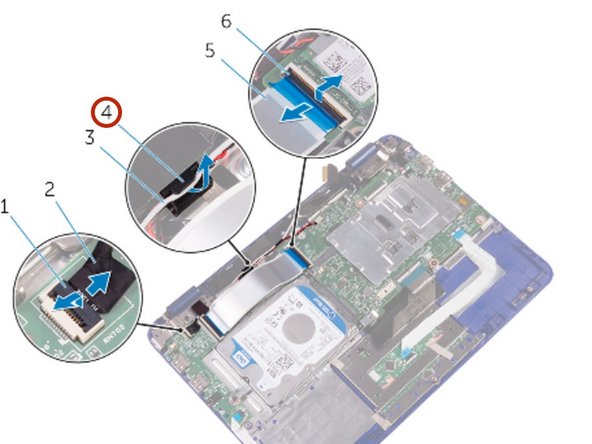
- Open the latch and disconnect the sensor-board cable from the I/O board.
- Remove the antenna cable from the routing guide on the right speaker.
- Open the latch and disconnect the I/O-board cable from the system board.
- Peel the tapes off the display hinges.
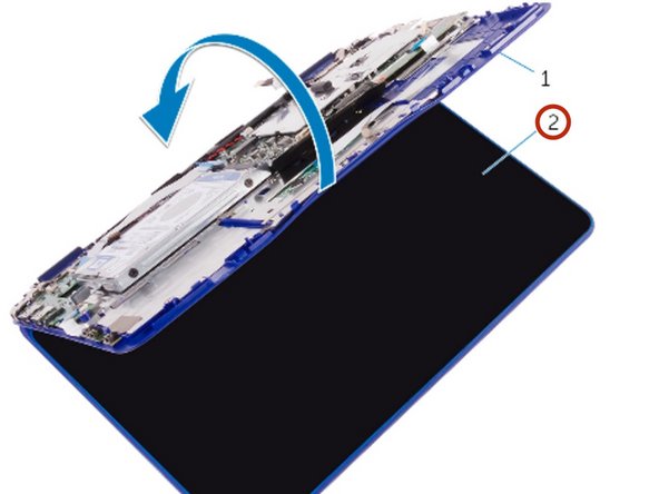
- Turn the computer over and open the display as far as possible.
- CAUTION: Place the computer on a soft and clean surface to avoid scratching the display.
- Place the computer face down on a flat surface.
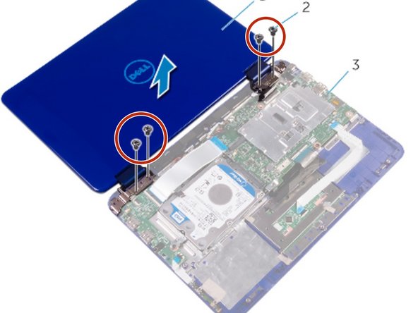
- Remove the screws that secure the display assembly to the palm-rest and keyboard assembly.
- Lift the display assembly off the palm-rest and keyboard assembly.
- Place the NEW display assembly on the palm-rest and keyboard assembly.
- Align the screw holes on the display hinges with the screw holes on the palm-rest and keyboard assembly.
- Replace the screws that secure the display assembly to the palm-rest and keyboard assembly.
- Turn the computer over and close the display.
- Slide the I/O-board cable into its slot on the system board and press down the latch to secure the cable.
- Route the antenna cable through its routing on the right speaker.
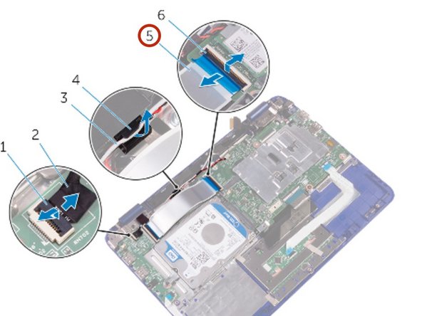
- Slide the sensor-board cable into its slot on the I/O board and press down the latch to secure the cable.
- Slide the display cable into its slot on the system board and press down the latch to secure the cable.
- Adhere the tape on the display cable.
- Align the screw hole on the display-cable bracket with the screw hole on the system board.
- Replace the screw that secures the display-cable bracket to the system board.