Huawei P10 Lite Display Assembly with Frame Replacement
ID: 108419
Description: Use this guide to remove and replace the...
Steps:
- Insert the tip of an opening pick between the back cover and the mid frame and slide it around the phone, to cut the adhesive.
- Using a suction handle to lift the back cover may help to get an initial gap for the opening pick to put in.
- If the adhesive is hard to cut, use an iOpener to loosen it.
- After you cut the adhesive on every edge, twist your opening pick, to separate the rear cover from the phone.
- Flip the rear cover over to the right side of the phone.
- Use a pair of tweezers to remove the sticker.
- Remove the two Phillips #00 screws.
- Remove the four 2.5 mm Phillips #00 screws.
- Use tweezers to remove the mainboard shield.
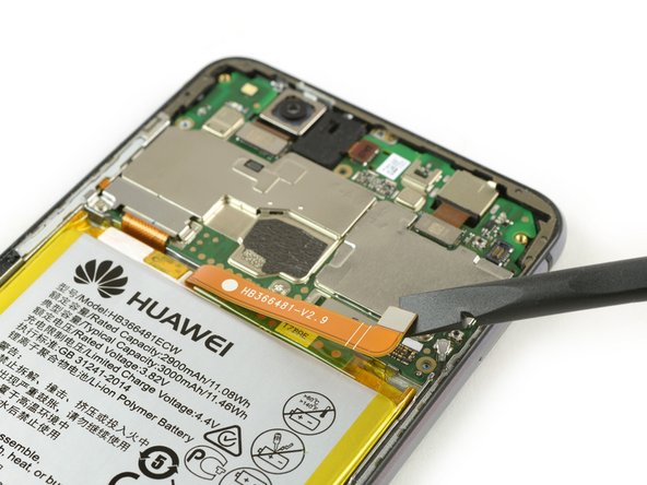
- Use the flat end of a spudger to disconnect the finger print sensor flex cable.
- When reassembling apply new adhesive where it is necessary.
- Remove the Phillips screw holding the battery connector plate in place.
- Remove the battery connector plate.
- Use the flat end of a spudger to disconnect the battery flex cable.
- Use an iOpener to loosen the adhesive beneath the battery.
- Insert a spudger between the battery and the mid frame to create a gap.
- Be careful not to puncture or crease the battery.
- Insert an opening pick or use the spuder in the gap to cut the adhesive beneath the battery.
- There are flex cables running under the battery. Don't damage them with your tools.
- Use a spudger to cut the rest of the adhesive and lever the battery out of the phone.
- Remove the battery.
- When reassembling your phone replace old adhesive with double-sided tape or pre-cut adhesive strips.
- Never reinstall a battery that has been bent or damaged during removal.
- Use a SIM card removal bit or tool and push it into the small hole in the SIM card tray.
- Remove the SIM card tray.
- Remove the two Phillips screws.
- Remove the display flex cable bracket with tweezers.
- Use a spudger to disconnect the headphone jack flex cable.
- Altough the headphone jack is not glued to the mid frame it is a little bit tucked in its bracket. Be careful not to damage it during the removal.
- Remove the headphone jack.
- Use a spudger to disconnect the rear camera flex cable.
- Remove the rear camera.
- Use a spudger to disconnect the volume and power button, the display and the main flex cable.
- Unplug the antenna cable with tweezers.
- The solder joints of some antenna cables might be weak so be careful not to break it out of the motherboard.
- Use an opening pick to pry out the motherboard until you can get a good grip.
- The front camera is still attached to the motherboard. Don't damage it during the motherboard removal.
- Remove the motherboard.
- On the back of the motherboard there are thermal pads (pink rubber-like gobs) for heat dissipation. If these thermal pads broke or are too dried out you might need to apply new thermal pads on the new display assembly or the motherboard.
- Remove the earpiece speaker with tweezers.
- Use tweezers to remove the plastic cover of the volume and power button flex cable.
- Use an opening pick to cut the adhesive between the volume and power button flex cable and the mid frame.
- The volume and power button flex cable is a little bit sticky and hard to remove. It can rip easily during the removal. You can use an iOpener to loosen the adhesive a little bit.
- Carefully remove the volume and power button flex cable with tweezers.
- Remove the eight Phillips #00 screws securing the loudspeaker.
- Insert an opening pick under the loudspeaker unit and lever it up until you can get a good grip.
- Remove the loudspeaker.
- Use the flat end of a spudger to disconnect the interconnect cable and remove it.
- Use tweezers to disconnect the antenna cable and remove it.
- Remove the charging board with tweezers.
- If you're having trouble whilst removing the charging board you can use an iOpener to loosen the adhesive beneath it.
- Before reassembly check your new part for any components that might need to be transferred from the old one. Also check if new thermal pads (pink rubber-like gobs) need to be applied.
- When reassembling your phone replace old adhesive with double-sided tape or pre-cut adhesive strips.