Panasonic LUMIX DMC-G8 (G80 G81 G85) disassembly and infrared filter removal
ID: 108574
Description: I needed to convert my camera to full spectrum...
Steps:
- Remove the SD card and the battery
- Photo 1: Remove the 7 mm screw (red) on the right side of the grip, as well as the 4 mm screw (orange) below the SD compartment door.
- Photo 2: Remove the 4mm screw on the left side of the camera (red) above the LCD hinge, as well as the 4mm screw above the USB port (orange)
- Photo 3: Remove all 5 mm screws circled in red, as well as the 4 mm screw (orange) and another 5 mm screw with a wider thread (yellow)
- Photo 1: Remove the two 2 mm screws below the viewfinder eyecup
- Then, remove the viewfinder cup with a heavy duty spudger from below.
- The viewfinder cup is firmly attached to the metal plate underneath it. Pressing the left and right sides of the viewfinder cup together while lifting the plastic part where the 2 mm screws are should make it easier.
- Photo 2: Remove the two 6 mm screws (red) and the two 4 mm screws of the metal plate that is holding the back panel against the viewfinder.
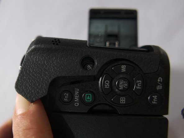
- Photo 1: You can start lifting the rubber corner of the thumb rest close to the back control dial.
- I did not have a plastic spudger for doing this, thus a flat screwdriver was used here but it will leave traces.
- Photo 2: Lift the thumb rest with your nails or a spudger.
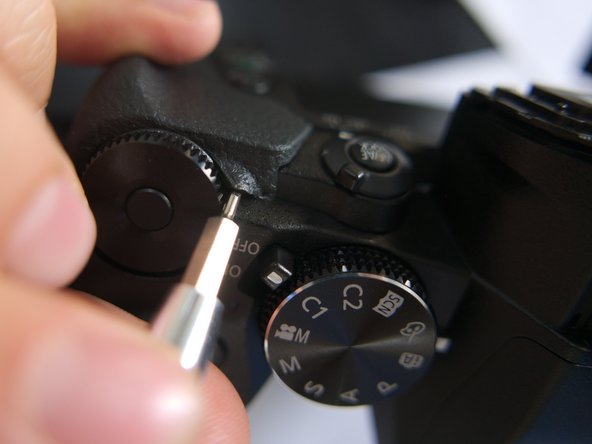
- Photo 1: remove 5mm screw marked in red square
- Photo 2: a last 5 mm screw sits under the rubber grip near the base of the camera
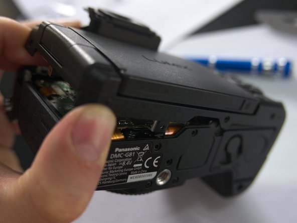
- Photo 3: now the back panel can be removed
- Slowly remove the back panel as the LCD and back buttons panel ribbon cables are attached to the underlying PCB. You can slowly put up the back panel vertically on the PCB and then comfortably release both ribbon cables with your nails.
- Further disassembly info welcome
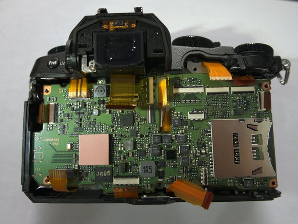
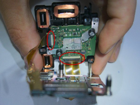
- Photo 1: Disconnect all visible ribbon cables, remove two 3 mm screws (red) at the left side of the PCB and two 5 mm screws (orange) at the right side of the PCB
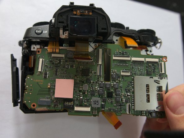
- Photo 2: View with all four screws and 11 ribbon cables disconnected
- Photo 3: Pull the main PCB out to the lower right corner
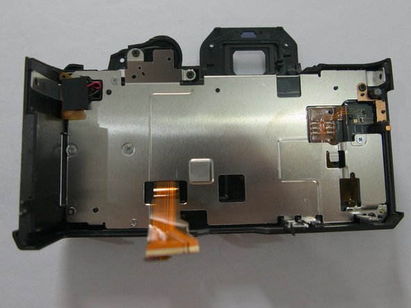
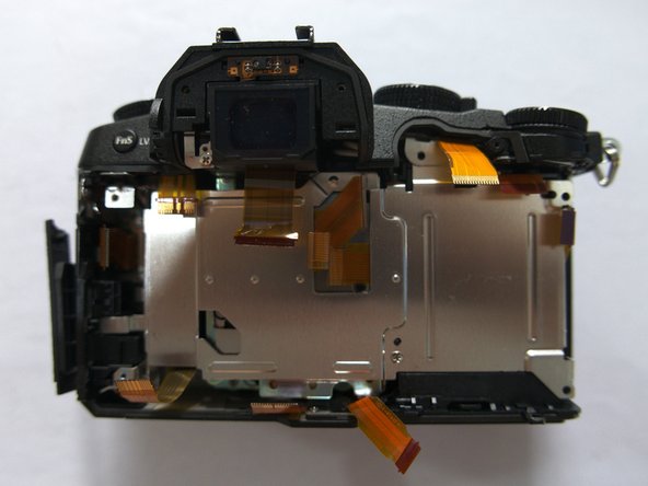
- Photo 1: Main PCB
- Photo 2: Metal shield
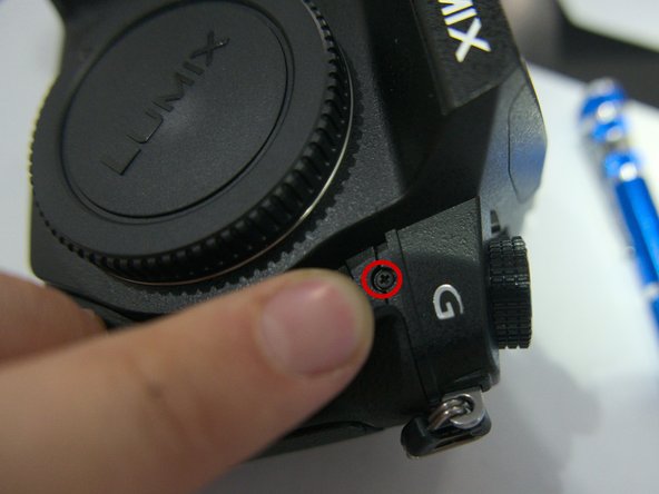
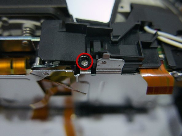
- Photo 1: Remove the 4 mm screw beneath the rubber below the left strap lug
- Photo 2: Remove the other 4 mm screw beneath the rubber below the G logo
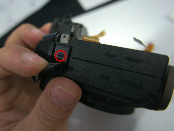
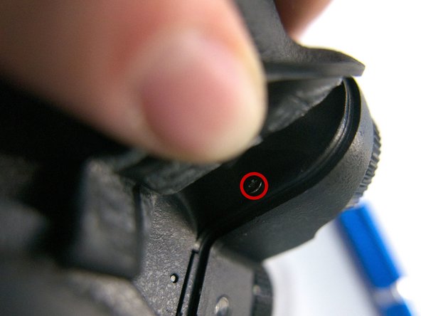
- Photo 3: Remove the 7 mm screw beneath the rubber below the shutter release
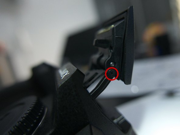
- Photo 1: Remove the 3 mm screw that is constraining the flash hinge movement.
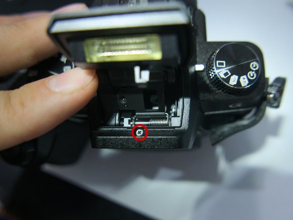
- Photo 2: Now hold the flash back to access a screw within the flash housing.
- This screw has to be removed but it stays attached to the flash housing
- Photo 3: The top panel can now be removed by pulling it up.
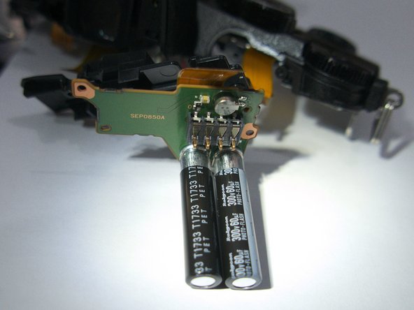
- The top panel is still attached to the flash batteries within the grip.
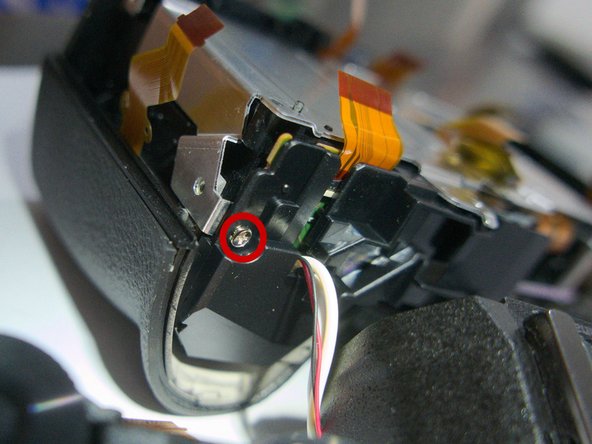
- Photo 1: Remove 4 mm screw holding the plastic plate above the flash batteries
- Photo 2: Remove a 5 mm screw holding the plastic plate
- Photo 3: the rest of the flash assembly can come off now
- Be careful not to short anything on the flash assembly!
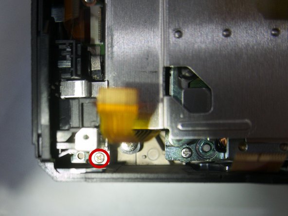
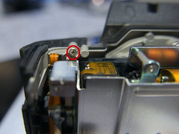
- Photo 1: Remove the 3 mm screw in the lower left corner
- Photo 2: Remove the 2 mm screw in the upper left corner
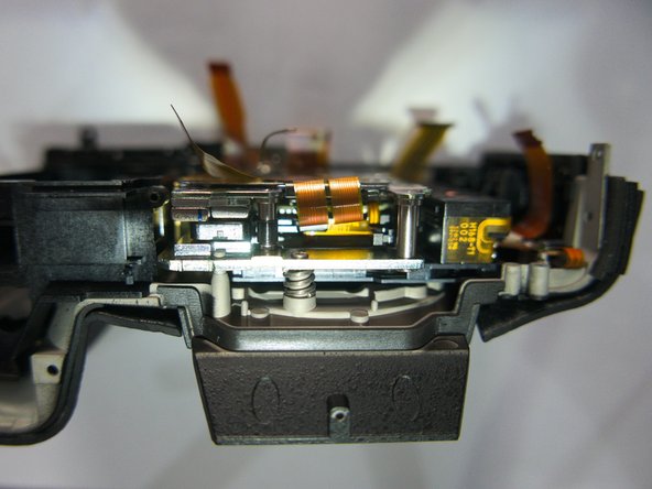
- Photo 3: The metal plate can now be pulled out
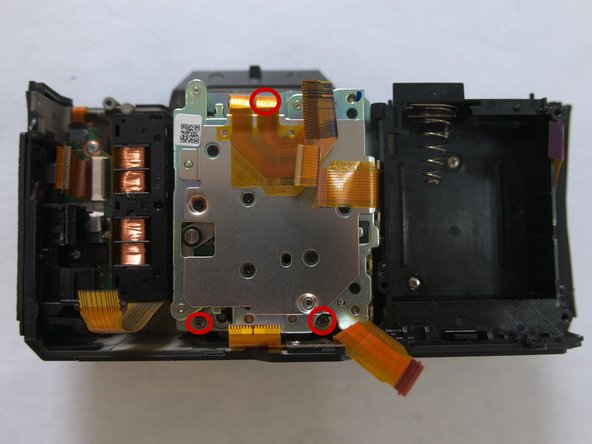
- Photo 1: Take a picture of the position of the sensor assembly relative to the metal nub
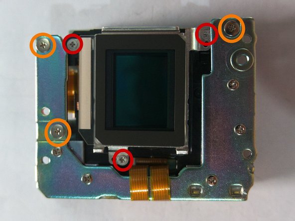
- Photo 2: remove three 7 mm screws that are holding the sensor assembly to the magnesium alloy front plate (one is hidden behind the ribbon cable)
- These screws regulate the position of the sensor relative to the focal plane. They are not maximally screwed in, they are rather at an intermediate position that corresponds to the position where the maximum focus point is at infinity and focus is uniform across the sensor.
- You can appreciably calibrate the placement of the sensor by screwing the screws in to the maximum point and counting how many turns and half-turns you unscrew them. It needed several re- and disassemblies to get the right placement, as I only got an approximate idea of the correct position with photo 1.
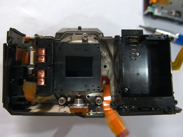
- Finally, pull out the sensor assembly
- Further disassembly information welcome
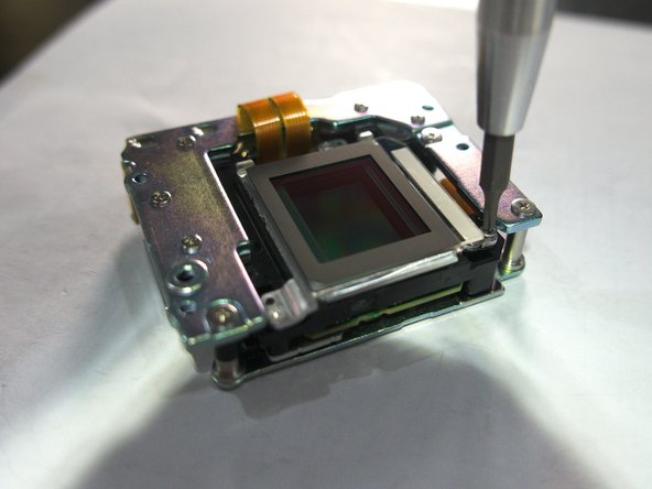
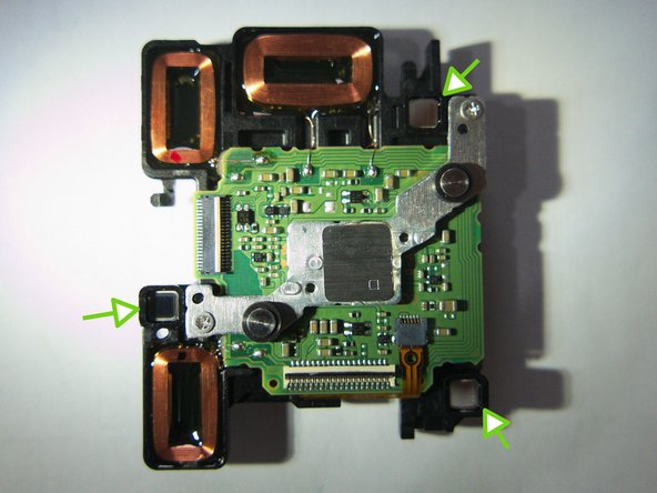
- Photo 1: Remove the three screws marked in red
- The screws marked in orange are removed later in this guide to disassemble the stabilization unit
- Photo 2: Do not press down too hard on the screws. The sensor PCB only rests on three tiny beads, and it also moves freely with them
- Photo 3: lift the metal cage holding the filters.
- There is a tiny ribbon cable connecting the outer glass plate to the sensor's PCB
- Anyone having an idea why the sensor PCB is connected to a glass plate via a ribbon cable?
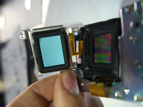
- The sensor is now exposed! There are multiple glass, metal and insulating sheet layers so be careful not to drop them
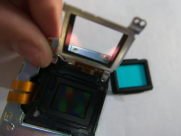
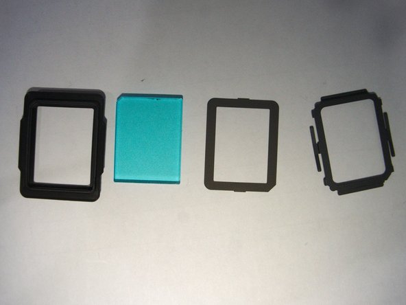
- Photo 1: There is a thin glass plate with a red tint glued tightly onto the metal frame. Below it is a thick bluish glass plate held within a rubber frame
- Both glass elements filter infrared. Removing the reddish glass plate resulted in some infrared sensitivity, and removing the second one gives most infrared sensitivity
- Removing the upper reddish glass plate is strenuous and the glass is likely to break
- Information as to which glass element filters what would be very useful. Possibly UV are filtered too, by why using two glass filters?
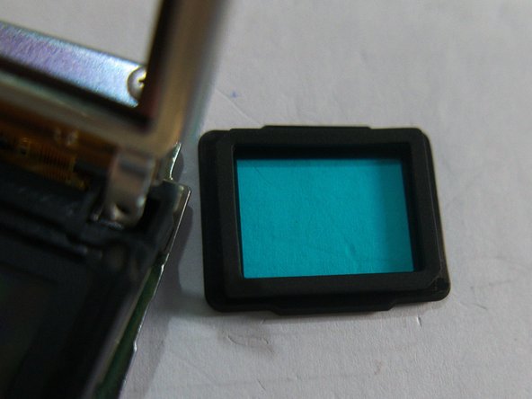
- Photo 2: close-up of the bluish filter
- Photo 3: breakdown of the blue filter assembly in layering order
- The blue filter has one slanted corner forcing it to be inserted with the correct side up (both sides are identical to the naked eye)
- Photo 1: Remove the three 4 mm screws marked in orange
- Opening up the stabilization unit is extremely fiddly and risky. There are strong magnets which might break your components when they snap together.
- Do not remove the unmarked screws, they simply hold metal spacers.
- Photo 2: Lift up the C-shaped metal plate and disconnect the two ribbon cables
- This metal plate is hard to lift and will snap to the underlying magnets. Hold it firmly without ripping off the ribbon cable that runs outside it.
- Photo 2: You can now pull out the sensor PCB from the stabilization unit
- The sensor PCB is lightly magnetically attracted to the lower plate of the stabilization unit. Note the three electric magnet coils regulating the sensor movement.
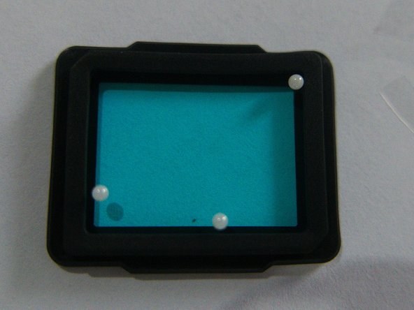
- The sensor PCB rests on three tiny beads, simply laid on three small metal enclosures below the PCB, indicated with green arrows. These beads are easy to lose!
- Photo 2: Close-up of the beads held inside the bluish filter, on which the sensor PCB rests to freely move.
- This camera is stated to have a 5-axis in-body stabilization on dpreview.com. I don't see how there could be more than 3 stabilised axes inside the body. The "5-axis hybrid" stabilisation as Panasonic states it, comes from the combination with the in-body, in-lens and electronic stabilisation.