Philips DVP642 Capacitor (C316) Replacement
ID: 113181
Description:
Steps:
- If your Philips DVP642 DVD Player does not turn on, but your standby light is flashing, a failed capacitor might be your problem. The C316 capacitor is a very common fault on this model Philips, but it may not be the fault with yours. This guide should help you determine if this fix is for you.
- Replacing the capacitor is easy and cheap. Your local Radioshack should have them in the store or you can purchase them online for about $.20 (digikey.com, mouser.com, jameco.com)
- Be sure to unplug your device from the wall BEFORE you open it.
- Remove 8 Phillips Head screws. There are 4 screws along the back and 2 on each side of the device.
- (Only the screws along the back that secure the lid need to be removed. Such as the one on the right in the first picture)
- There are 2 screws on each side.
- Remove the top of the device. It should lift right up.
- This is a good time to inspect the underside of the lid for clues. Pictured is the lid from another player with a no power issue. The failed components left a burn mark right above them.
- Take care not to touch any of the components on the Power Supply Board. There could still be high voltage present.
- The power supply board is the tan colored circuit board.
- There are 3 ribbon cables that need to be disconnected. One can only be disconnected at the Main Board. (green)
- Unscrew the 3 mounting screws and release the 4th corner of the board from the plastic standoff using a pair of needle nose pliers.
- Here's a better view of the plastic piece with the board removed. You're just squeezing the two little "wings" together while pulling up on the board. Be patient, it can be a little tedious.
- Capacitors can store large amounts of electricity. It is advised that you take the time to discharge them using the proper tool and not just a screwdriver. Touch both leads with a resistor to do this safely.
- Use a multimeter to ensure that each capacitor is fully discharged.
- If the top of the capacitor is bulging (or completely blown out) this is an indication that the capacitor has failed.
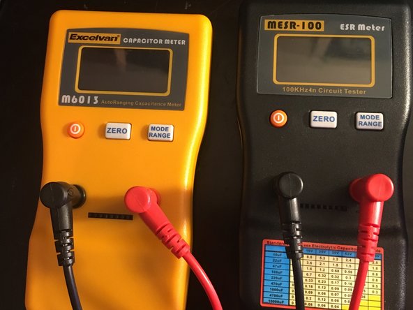
- If the capacitor is not bulging, it could still be bad. You can test this using a capacitance meter or an ESR meter.
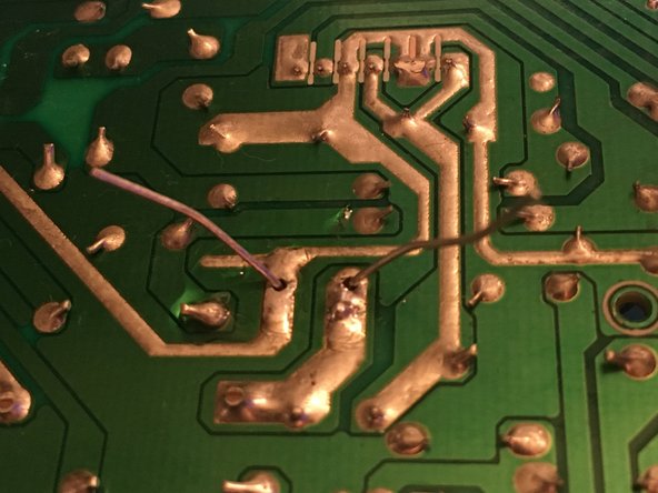
- The two joints indicated in the picture are the ones you need to desolder.
- Add a little bit of flux to the solder joints and tin the tip of your soldering iron.
- When the solder melts, use the desoldering tool to remove the solder.
- Remove the old capacitor
- Be conscious of the orientation of the new capacitor. Electrolytic capacitors like this one are polarized and will only work in one direction.
- Notice that I am using a capacitor with the same capacitance, but a higher voltage rating. This only increases the voltage the capacitor can handle before failing, it does not raise the voltage of the circuit. It is important not to use a lower value, however. Be sure to use the correct capacitance (1000uF).
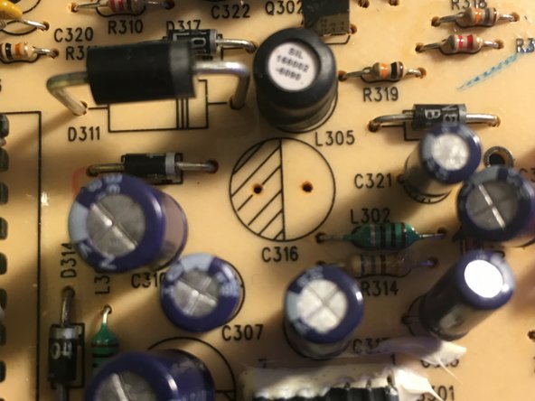
- The grey line indicates which side is negative. The negative side also typically has a shorter lead. On the board, the "shaded" half of the circle with the hashmarks is the negative side.
- Insert the new capacitor and bend the legs outward to help hold it in place when you turn the board over.
- Solder the leads and clip the excess length.
- Reassembly is the reverse of the disassembly process. Don't forget to reattach the ground wire under the screw that secures the board.