Teardown: Breville Toaster
ID: 113330
Description: This teardown is done as to comply with the...
Steps:
- Breville Toaster.
- The toaster before the teardown process.
- Turn the toaster upside-down.
- Use the drill to unscrew the six slotted Spanner head screws
- Use the drill with corresponding screwdriver bit to remove the Truss Phillip screws
- The Slotted Spanner head screws hold the four rubber feet at the bottom of the casing.
- Unattach the four rubber feet.
- Detach the timer knob using a flat head screw driver
- Remove the internal components from the red casing
- Note: Red casing is still attached to the interior body of the toaster.
- Detach electric circuit housing from red casing
- Firstly, unscrew the four Pan Phillip head screws
- Then snap off the three welded plastic studs to detach the timer knob housing from the red casing
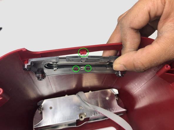
- Unfasten the two Pan Phillip head screws to detach the buttons' housing
- Note: There are two housings attach to both side of the interior body of the toaster.
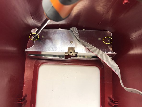
- Remove the two Pan Phillip head screws to detach the circuit board from the heat controller housing.
- Then, remove the slider as well.
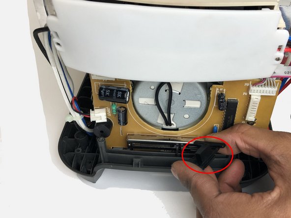
- Remove the circuit board housing for the heat controller from the interior body of the toaster by unscrewing two Pan Phillip head screws
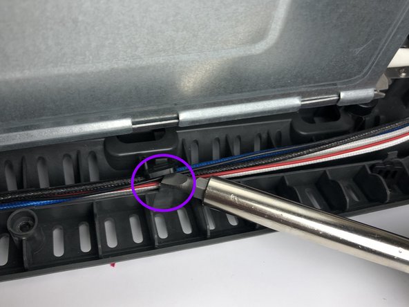
- Remove the cable fasteners using a flat head screw driver
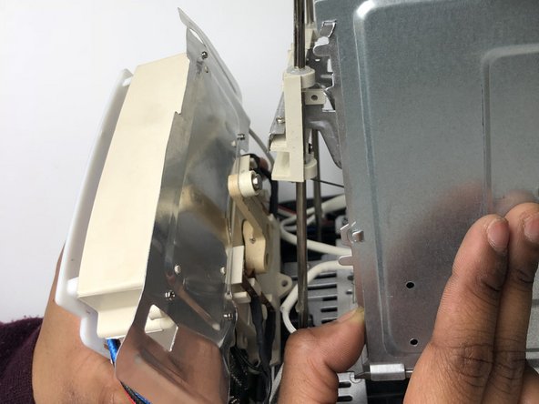
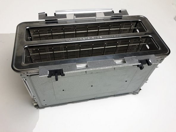
- Separate the interior body of the toaster from the bottom cover.
- Remove the screw caps
- Unscrew the two Pan Phillip head screws to detach the aluminium vent
- Use pliers to break apart the welded wires from the interior body.
- Snip off the rest of the wires still attached to the interior body using a wire cutter
- Remove the circuit board from its housing
- Separate the electric components from the interior body
- Insert wisdom here.