Nintendo Switch Left Joy Con Sensor Rail Replacement
ID: 113429
Description: Follow this guide to replace a broken or faulty...
Steps:
- Before you begin this repair, make sure the device is completely powered off.
- Press and hold down the small round button on the back of the Joy Con controller.
- While you hold down the button, slide the controller upward.
- Continue sliding the Joy Con upward until it's completely removed from the console.
- Repeat this same process for the other Joy Con.
- Use a Y00 screwdriver to remove the four 6.3 mm-long screws securing the rear panel.
- Throughout this repair, keep track of each screw and make sure it goes back exactly where it came from.
- If you do happen to strip one of the four 6.3 mm-long Y00 screws, If you are lucky and careful, you may be able to use a Y0 bit to remove the screw(s). Please note that if you do attempt this, a bit of extra pressure will need to be applied to the screwdriver so that the screwdriver bit catches the screw.
- If you do end up removing the stripped screw with this method, PLEASE do not reuse the screw again and instead replace the screw.
- Use a JIS 00 driver to remove the following screws securing the rear panel:
- One 2.5 mm-long screw on the top edge of the device
- Two 2.5 mm-long screws on the bottom edge of the device
- To prevent these tight screws from stripping, apply firm downward force, work slowly, and try another JIS 00 driver if the screws won't come out. Make sure the driver is fully inserted.
- You can use a Phillips #000 screwdriver in a pinch, but you risk damaging or stripping the screws. Push down firmly on the screwdriver and twist slowly. Often, switching drivers may help, even if they are the same size.
- Use a JIS 00 driver to remove the two 3.8 mm center screws on the sides of the device (one on each side).
- Use your finger to flip up the kickstand on the back of the device.
- If there's a microSD card in the microSD card slot, remove it now before you continue to the next step.
- Use a JIS 00 driver to remove the 1.6 mm screw in the kickstand well.
- Close the kickstand.
- Open the game card cartridge flap.
- The game card cartridge flap attaches to the other half of the plastic shell, preventing you from completely lifting up the rear panel if it's closed.
- Lift the rear panel straight up from the bottom of the device and remove it.
- Don't tilt it upwards while opening or else you risk breaking the plastic tabs on the top edge of the panel.
- Use a JIS 00 driver to remove the 3.1 mm screw securing the microSD card reader to the device.
- Use your fingers or a pair of tweezers to lift the microSD card reader straight up from the device to disconnect and remove it.
- During reassembly, remove the foam pad before connecting the press connector to the motherboard. Set the foam pad back in place after you verify it's connected.
- Use a JIS 00 driver to remove the six 3 mm screws securing the shield plate to the device.
- If the console doesn't have this foam, skip this step.
- Use your fingers or a pair of tweezers to peel back the piece of foam on the top edge of the device near the fan exhaust port.
- If the foam doesn't easily peel away, don't force it as it might end up tearing. Carefully peel at different spots to pull back the foam.
- Insert a spudger underneath the shield plate along the edge of the device.
- Pry up to lift the shield plate and remove it from the device.
- You may feel a bit of resistance. This is normal, since the shield plate is slightly bonded to the heat sink with thermal paste.
- A thick pink thermal compound bridges the gap between the shield plate and the copper heat sink underneath. This helps prevent the Switch from overheating.
- During reassembly, if you don't have replacement thermal compound, use the flat end of a spudger to distribute the old compound evenly across the heat pipe, as thick as possible to ensure proper contact. Repeat this process on the shield plate.
- If you need to replace it, refer to our thermal paste guide to remove the old thermal compound and replace it with an appropriate compound, such as thermal putty or K5 Pro, during reassembly.
- Use the point of a spudger to pry the battery connector straight up and out of its socket on the motherboard.
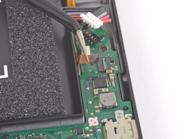
- Use an opening tool, spudger, or your fingernail to flip up the small, hinged locking flap on the Joy Con rail data cable's ZIF connector.
- Use a pair of tweezers to slide the Joy Con rail data cable out of its connector on the motherboard.
- Use your fingers or a pair of tweezers to lift the battery connector up and out of the way of the Joy Con rail's data cable.
- Use your fingers or a pair of tweezers to slide the Joy Con rail data cable out from under the motherboard.
- Use a JIS 00 driver to remove the four 3.7 mm screws securing the left Joy Con rail to the frame of the device.
- These screws are torqued down and can be difficult to remove. To prevent them from stripping, apply firm downward force, work slowly and try a different screwdriver if the screws won't come out.
- Remove the left Joy Con sensor rail from the device.