Nikon 1 J5 Teardown (repair purpose)
ID: 113614
Description:
Steps:
- Remove Lens, MicroSD Card and Battery
- Remove 2 screws first
- Lift the cover
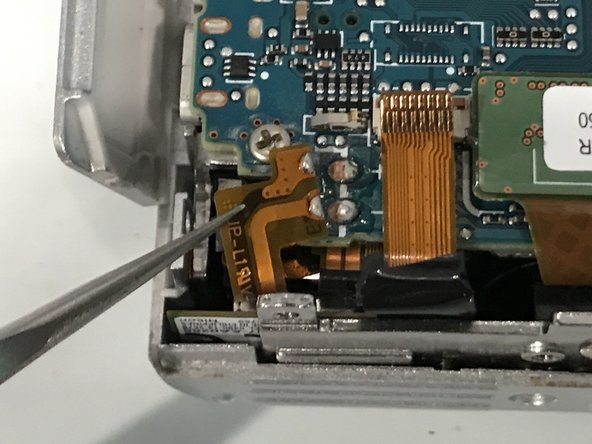
- Disconnect LCD FPC
- Then remove 4 screws
- Remove LCD assembly
- Insert wisdom here.
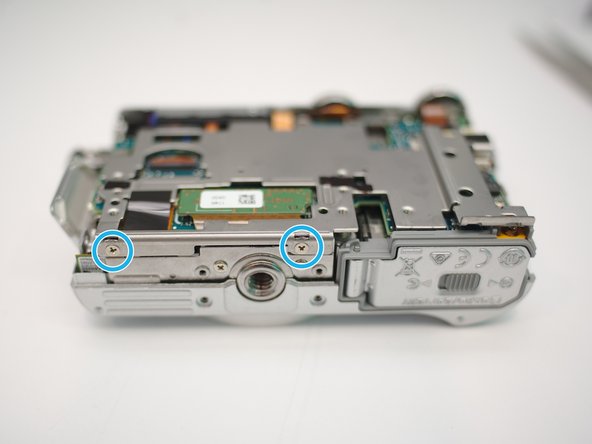
- Remove 2 screws
- Open connection bay
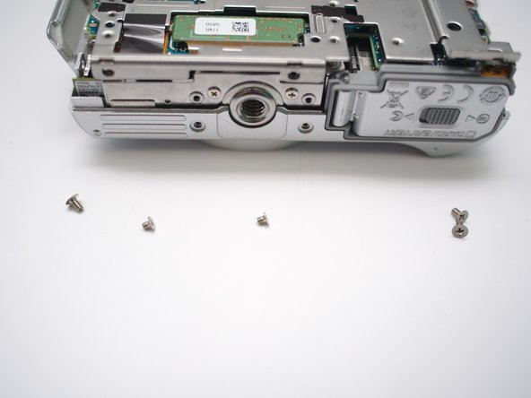
- Remove 2 screws
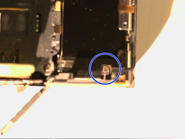
- Remove 1 screw under the DC power cable notch cover
- Remove 4 screws and be ware the length difference
- Peel the rubber open from right hand side
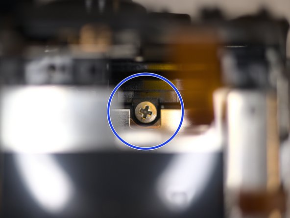
- Remove 1 screw
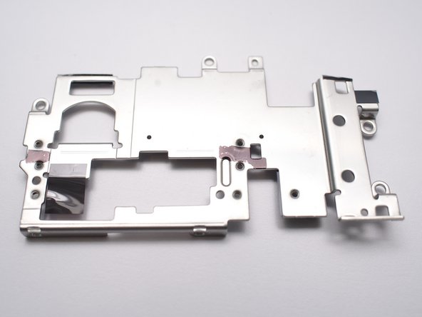
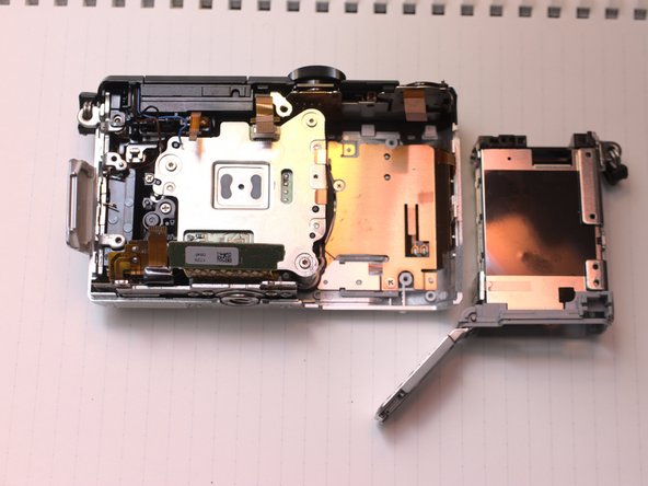
- Now the back case can be removed.
- There's no fragile FPC or cables in this step. Just be patient.
- Disconnect speaker cable
- Pull out keypad cable
- Insert small crowbar or flat head screw driver here to lift the keypad up.
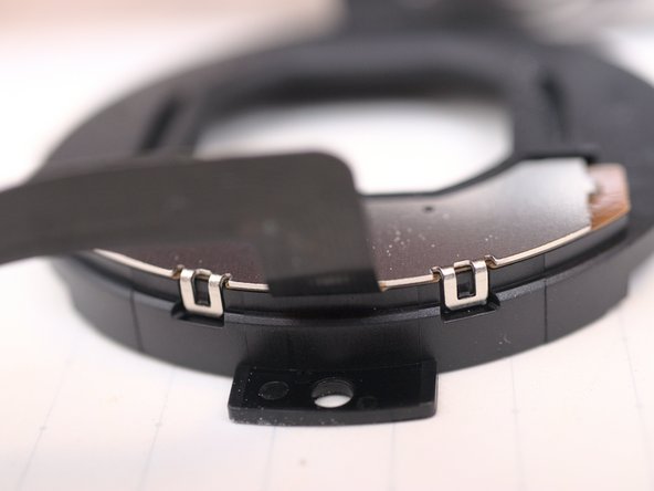
- Those clips are very tight.
- Remove 3 screws
- Remove 2 screws
- Notice the sizes of screws
- Need some tape peeling
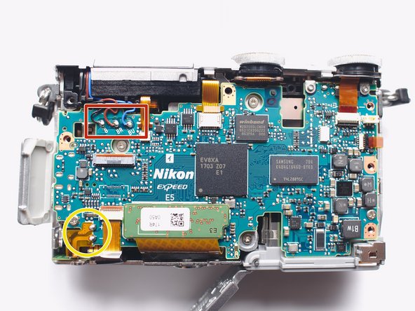
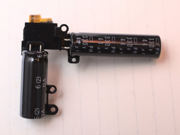
- Dangerous DC Voltage > 200V, stored in a 330V 80uF capacitor set.
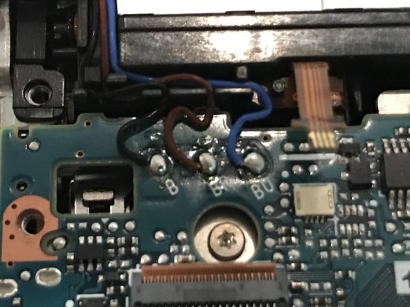
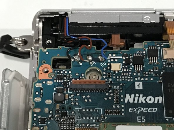
- Flash xenon tube terminals, positive connected to capacitor, negative controlled by circuit, and a trigger signal.
- Use 10kohm, >2W resistor, connect 2 solder joints for more than 5sec. These are flash condenser/capacitor terminals. DO NOT discharge by SHORT them. (Note 2020-10-13)
- DMM's Low-Z voltage works even better, also safer.
- Measure voltage between 2 solder joints to ensure voltage <10V
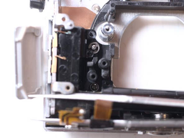
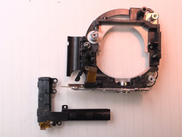
- Flash solenoid and detecter
- Microphones and AF assistant LED
- Keypad
- Switches
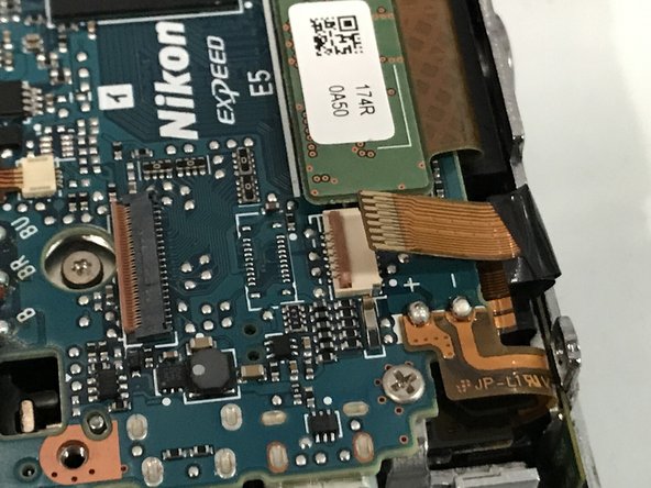
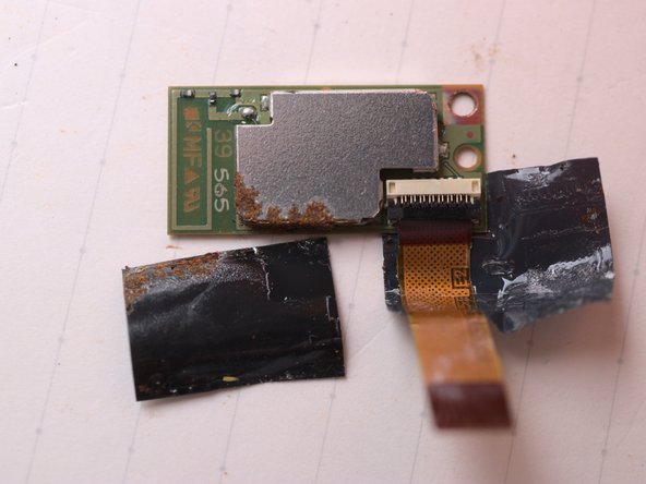
- NFC
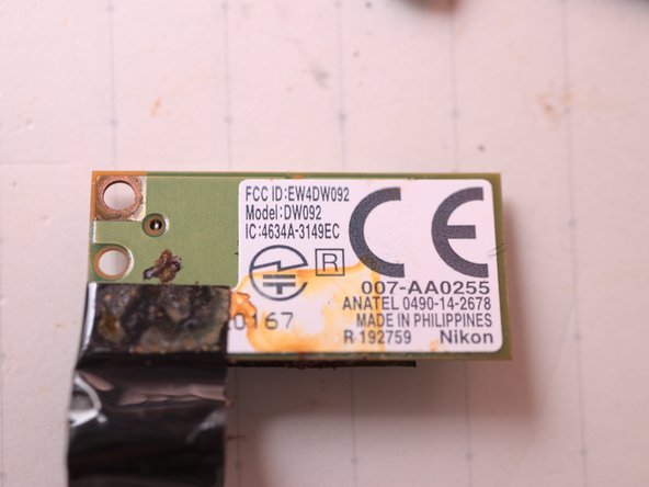
- WiFi and Bluetooth, Lens(back)
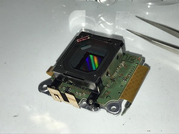
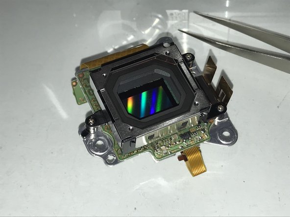
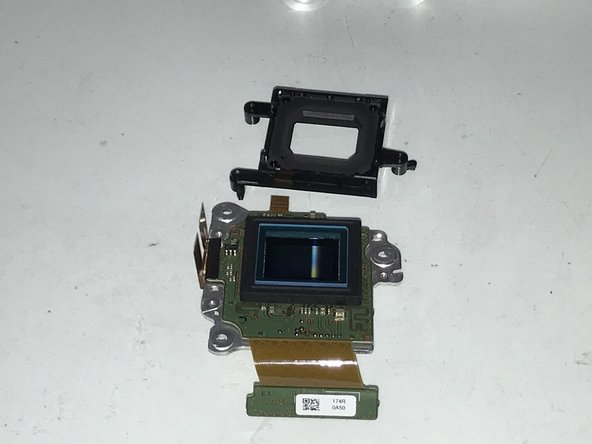
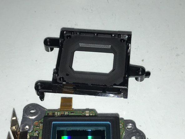
- CMOS sensor
- LCD
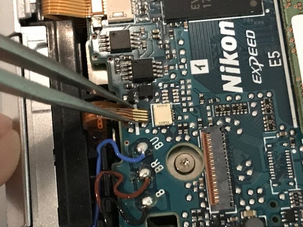
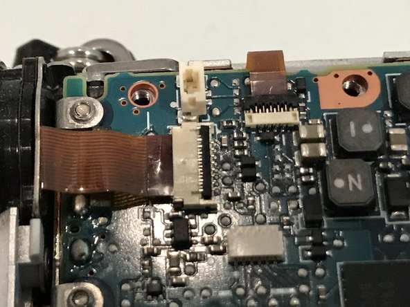
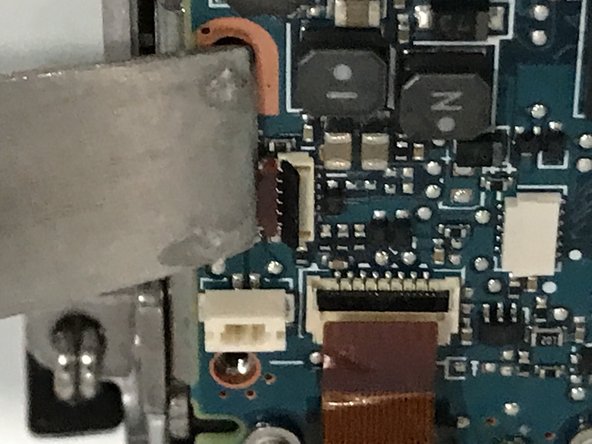
- Detach every FPC you can find
- Detach every FPC you can find
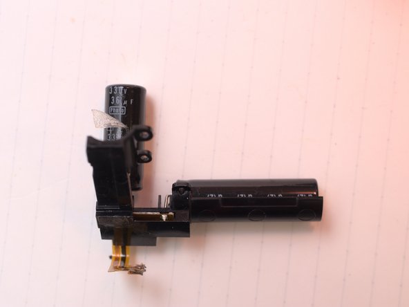
- Desolder flash condenser FPC and Flash cables (remember to discharge first)
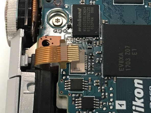
- More FPC
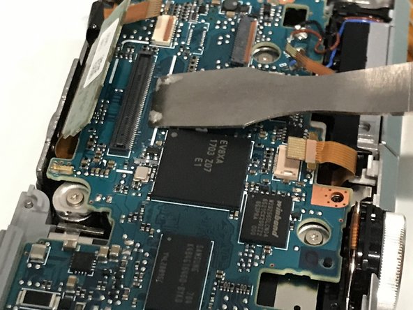
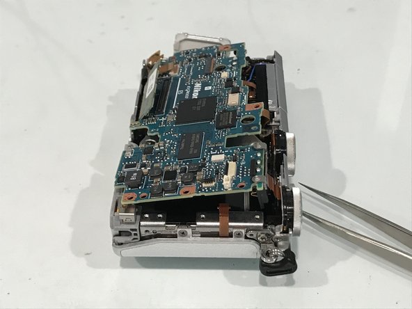
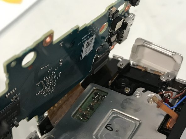
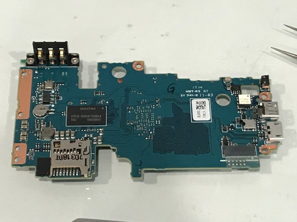
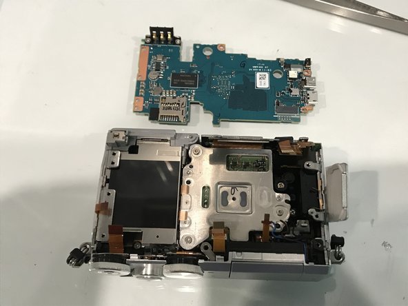
- Lift Main PCB, SLOWLY and GENTLY
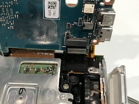
- One more FPC at the back side.
- Insert wisdom here.
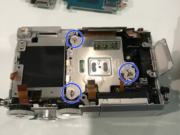
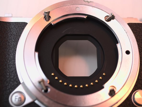
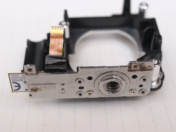
- Mark 3 screws for their ID and position.
- Also record how many turns to the limit.
- Measure and record distance to front flange if possible.
- These screws will affect focus focal plain.
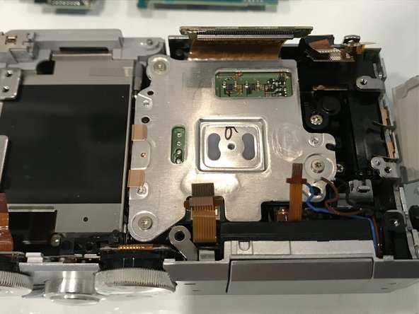
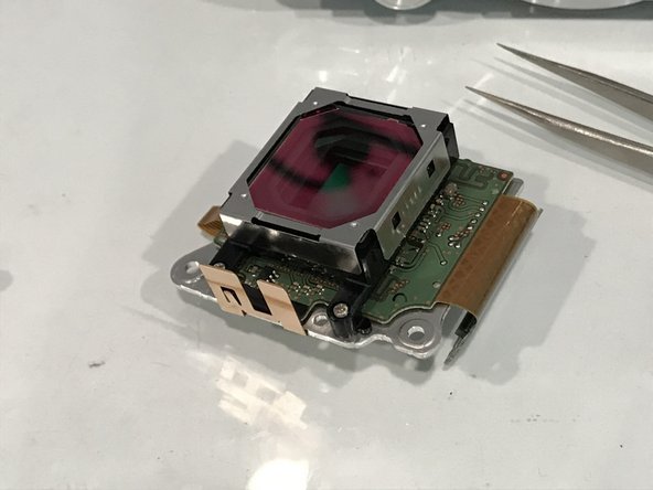
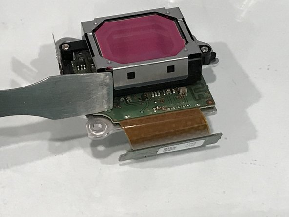
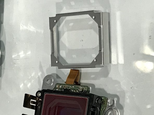
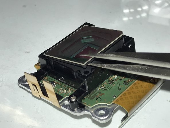
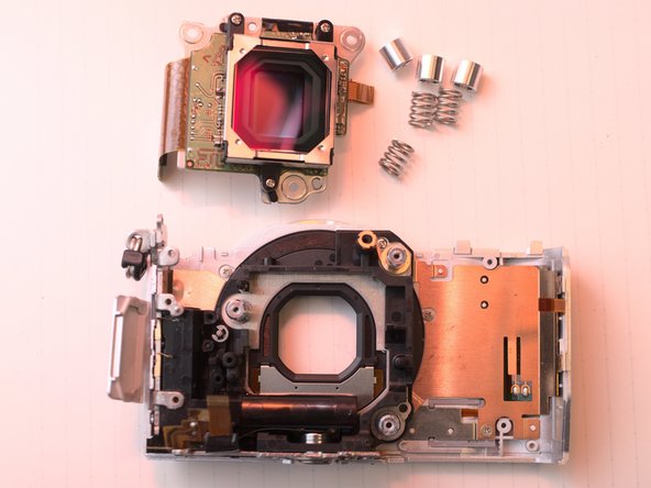
- Sensor module and IR-cut filter
- Hold the IR-cut filter by its edge, to avoid scratches and contamination.
- Use plastic tweezers can avoid scratches.
- And I don't quite remember what is this filter/window.
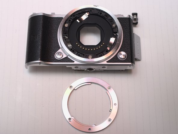
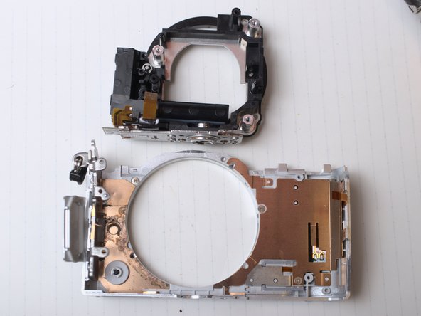
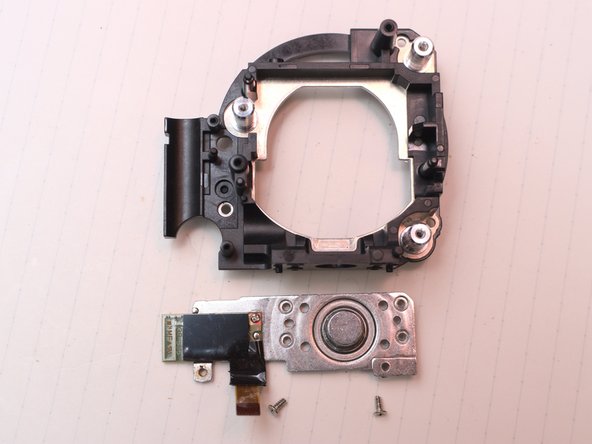
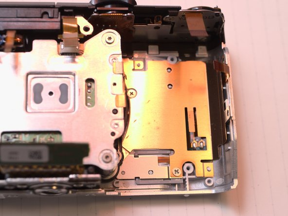
- remove 2 self tap screws (upper and lower)
- Sorry for the magical color change of victim camera and chaotic white balance on of my desk(mixed warm LED and flash).
- Insert wisdom here.
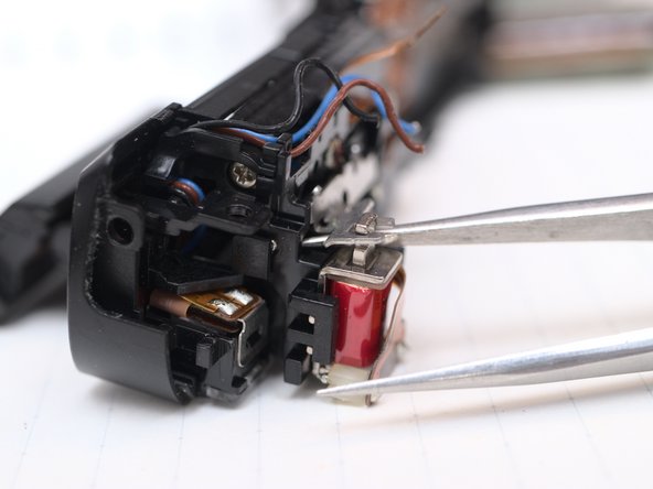
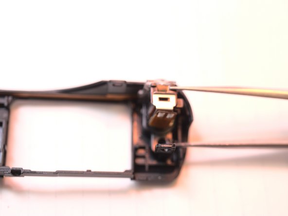
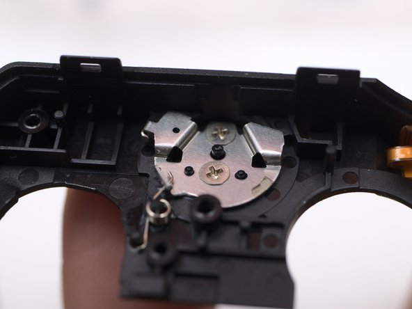
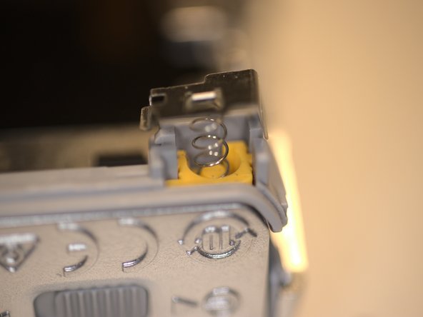
- Pop up flash by pulling up the solenoid
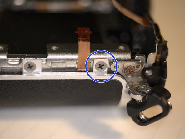
- Remove screw in flash bay
- Remove 2 self tap screws
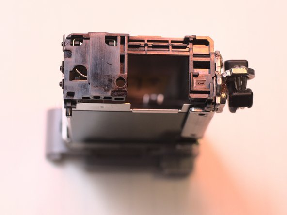
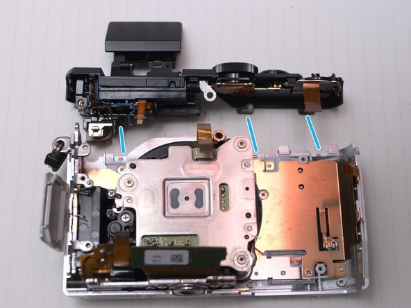
- Now you can wiggle off top case.
- Only 3 small clips
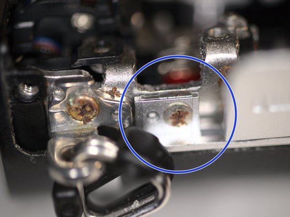
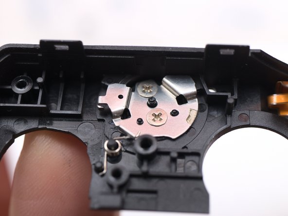
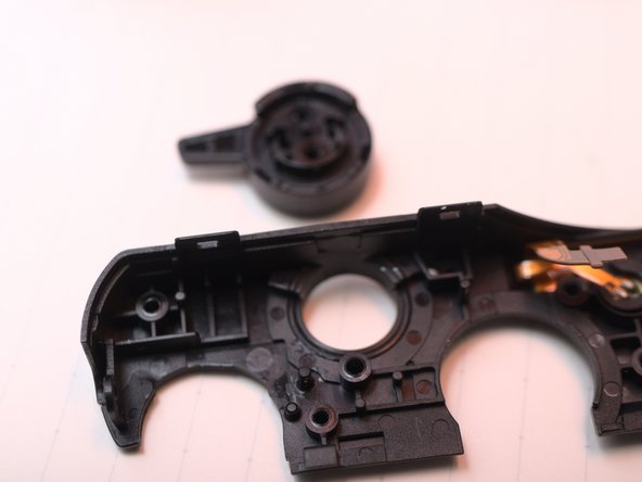
- Remove this screw
- Remove flash head
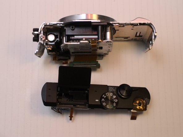
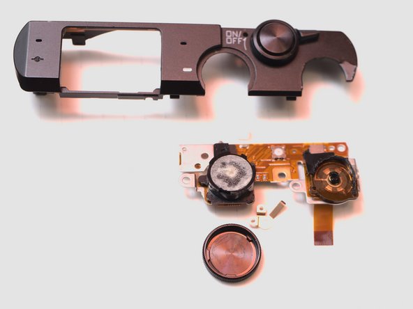
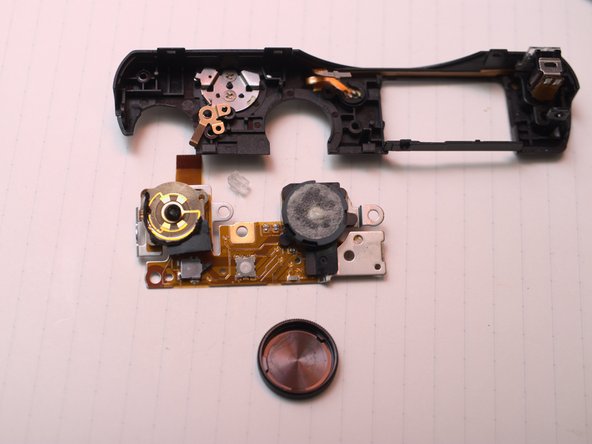
- Top Case
- AF assistant LED and left Microphone
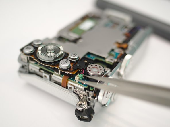
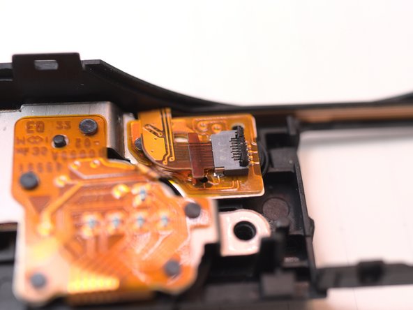
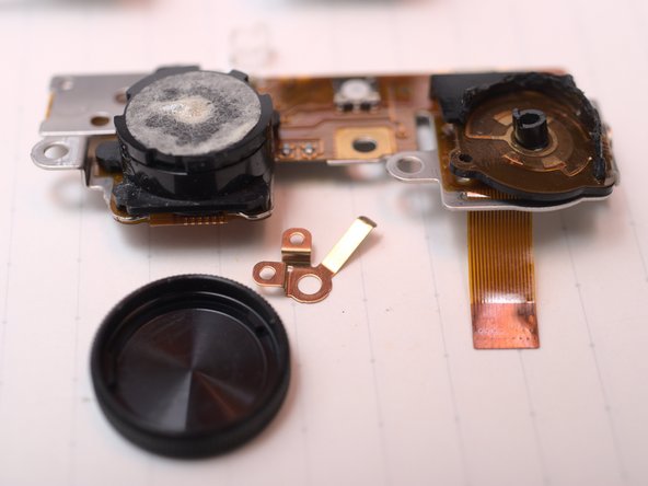
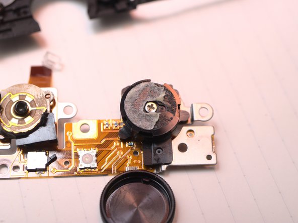
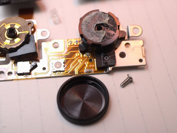
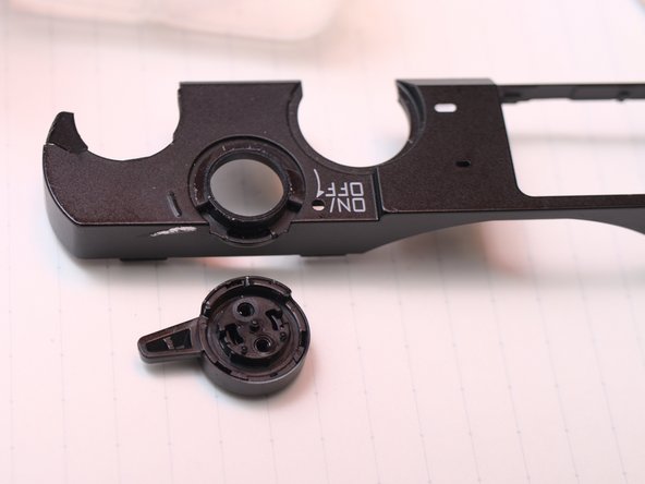
- Switch board. Right microphone, power switch, shutter button, mode dial, main command dial.
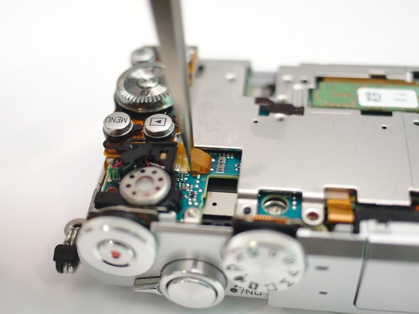
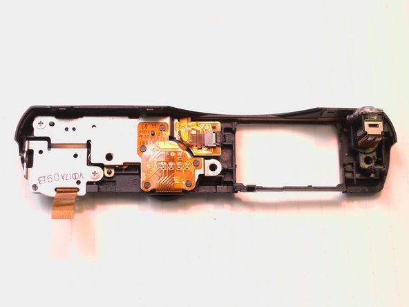
- screws
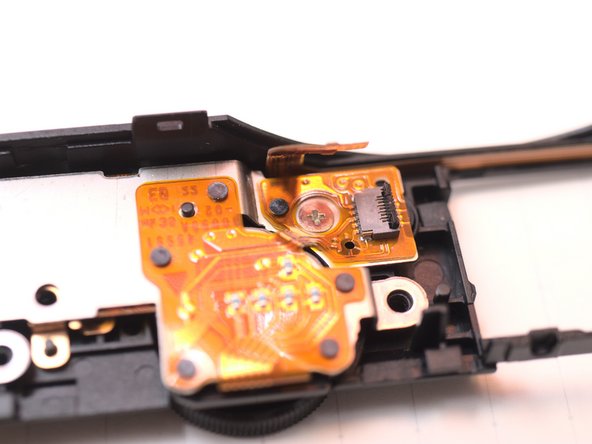
- FPC
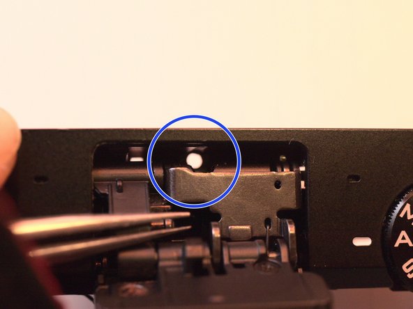
- Sneaky screw
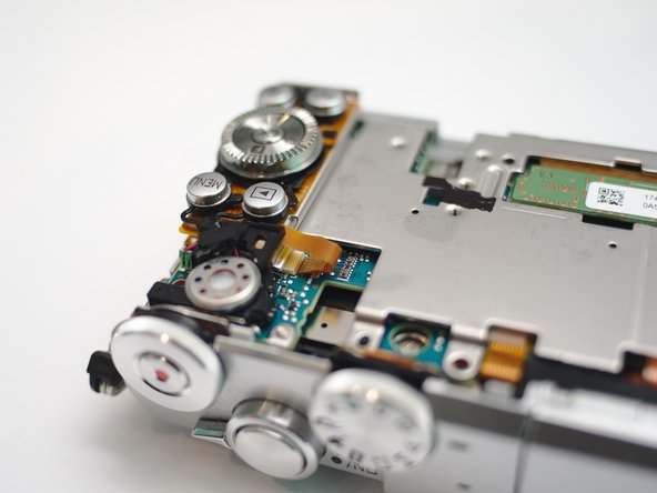
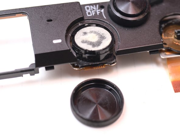
- Mode dial cap is double sided taped,
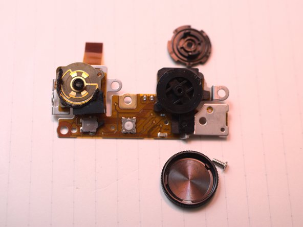
- Remove switch board.
- Someone else already murdered the main dial and video record button...
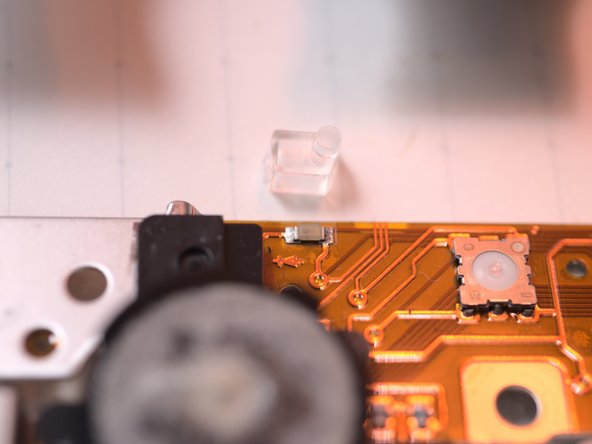
- Light guide
- other angles
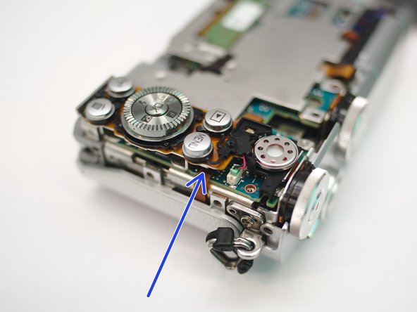
- Sneakier screw
- sc...s
- Focus adjust and focal plane calibration is important to par-focal lenses
- Insert wisdom here.
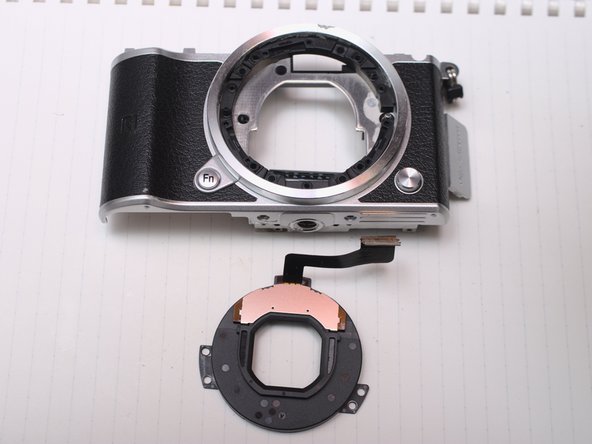
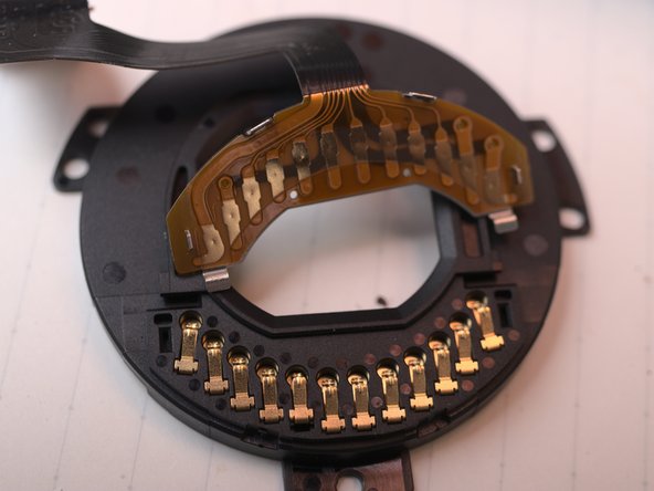
- and lens contacts
- Insert wisdom here.
- Insert wisdom here.
- Capacitor / condenser, which do you prefer?
- WiFi and bluetooth
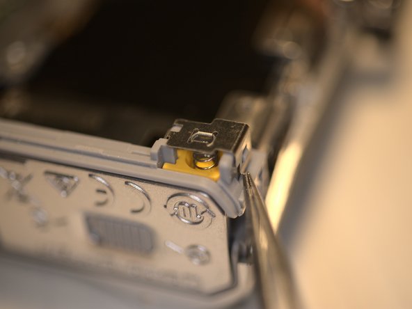
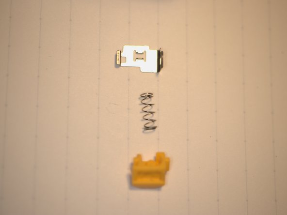
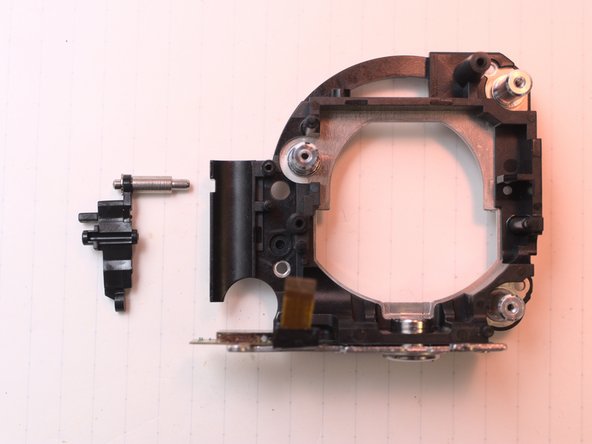
- Lens latch pin
- This one is liquid damaged
- under the shield
- Insert wisdom here.
- Insert wisdom here.