Breville "Control Grip" Immersion Blender Teardown
ID: 113689
Description: This teardown guide indicates the necessary...
Steps:
- Initial Spec and Model Rundown
- Breville "Control Grip" Immersion Blender - (Model BSB510)
- Dimensions - 10 x 5.6 x 22.4 cm
- Construction Materials - Stainless Steel Blending Shaft
- Variable Speed Control Settings - Adjustable 15 setting speed control for precise blending and processing.
- Power - 700 Watts
- Voltage - 220–240 Volts
- Depicted here are the individual components of the immersion blender that will be separated during this teardown.
- As you may see, the casing has been sawn just above where a plastic weld was located keeping the insides secure. This allows you to access the main components, like the motor assembly for example, but is irreversible and may cause performance issues.
- Make sure to begin the teardown in a well lit and clean environment with lots of space to ensure you are able to remove and set aside pieces with ease. (A zip-lock bag is optional to hold some of the smaller pieces in the teardown such as screws, etc.)
- Later on we take the product into a workshop to be able to saw through the casing, however this is optional if your concern is safety and cleanliness during the teardown.
- Press into the two buttons located on the outside of the product to release the metal immersion blender stick.
- This immersion stick cannot be taken apart without destructive or specialist tooling and therefore we are focusing on the main components found in the blender motor casing.
- To remove the speed adjustment dial first turn the cap onto the number 15 speed adjustment as this gives more room under the cap at the front to pry it off.
- Next grab a flat-head screwdriver and wedge it under the dial on the front side opposite of the wiring.
- This step requires a bit of force. Carefully start prying the cap off by levering the screwdriver around the front edge to pop it out.
- The top cap of the blender is held in by two screws that were located under the adjustment dial.
- Simply unscrew these and place them aside as you wish and you are then able to remove the cap with ease.
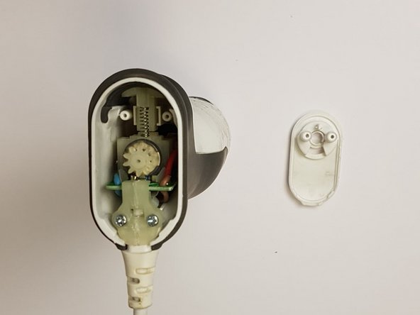
- Further two screws can be found under this top cap that hold in a plastic moulded PCB and wire holder.
- Simply unscrew these from the product and set them aside as you wish.
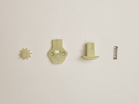
- Remove all plastic pieces and the spring. Twist the gear and pull gently to remove.
- Remove all the components depicted in the image by simply lifting each piece upwards.
- The spring can be compressed and removed and the gear requires a twist and gentle pull to take out.
- A zip lock bag may come in handy now as the small components can be easily lost.
- Note: Some plastic pieces are attached to the PCB and can't be removed.
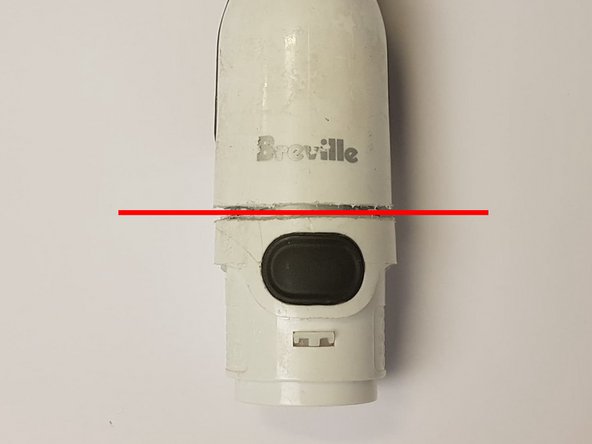
- This step will damage your product but is the simplest and most effective way to access the motor components/PCB as the case is plastic welded to minimise moving parts when the blender is in use.
- Begin by taping the circumference of the shell above the release buttons.
- Draw a line around the shell with a marker, 5mm above the two release mechanisms.
- Using a hacksaw, gently slice back and forth along the line while rotating the casing, making sure to stop at the surface of the metal component inside, this is the motor.
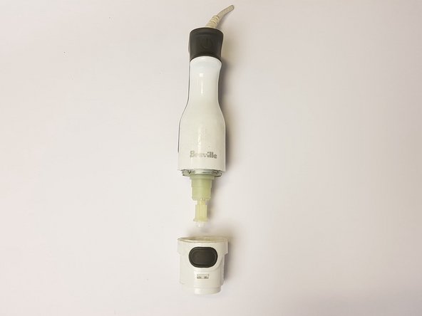
- To access the main components all that is left is to remove the bottom section that we had just cut.
- This step may require a bit of force, some prying around the edges, or even heat as the section above the plastic weld may still be stuck or there may be adhesive still holding the motor to the outer casing to reduce internal vibrations.
- Now the bottom section is removed you may simply slide the main components out from the bottom as one piece.
- Ensure the wire is disconnected from the top to allow the assembly to slide through.
- The last part that can be removed is a small plastic component at the bottom as indicated.
- This is a list of components that you should have at the end of the teardown.