LeapFrog LeapPad Ultimate LCD Screen Replacement
ID: 115602
Description: The screen of any device is one of the most...
Steps:
- Flip over the Pad to its back side to begin the removal of the back panel.
- Begin by removing the blue rim along the edge of the device. It runs along the green silicone lining.
- This is very difficult to remove , so do be patient. To help remove the seal, both a metal spudger and plastic opening tool may be used.
- Remove the pen from its place before starting to avoid tangling.
- Once the blue rim is removed, the 12 screws will be visible.
- Use the Phillips #1 screwdriver to unscrew all 12 screws.
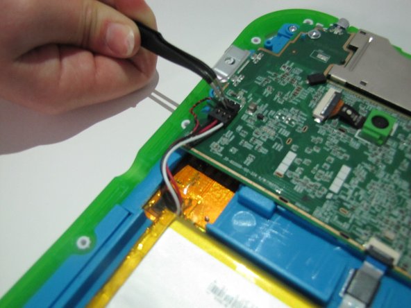
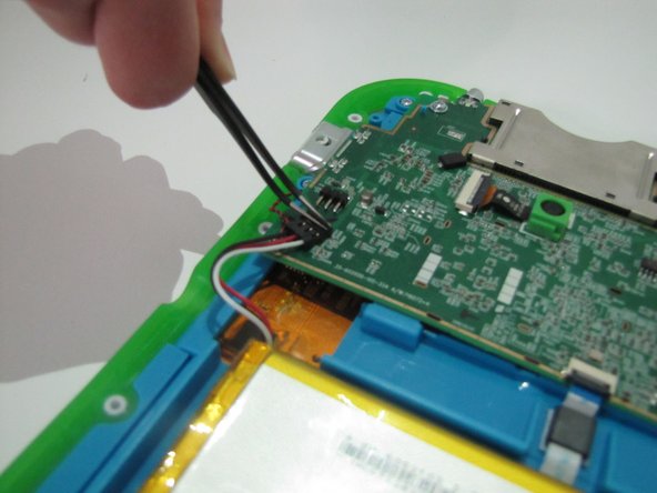
- The segment connecting the battery to the motherboard will consist of red, white, and black wires.
- There is a small notch on the segment. Use the curved tweezers to pull the notch in the direction of the battery. this will disconnect the battery from the motherboard.
- The battery is the bright orange rectangle.
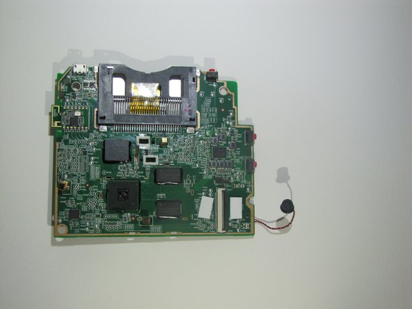
- The motherboard is the large dark green surface.
- Carefully remove the battery from its place and set aside.
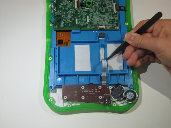
- Removing the battery will fully expose a white and blue ribbon cable that runs beneath the battery.
- The ribbon cable must be disconnected from the motherboard and removed from the panel.
- The ZIF connector which connects the ribbon cable and the motherboard has a small flap on the top.
- Use the curved tweezers to to flip the flap up.
- Once it is disconnected, carefully pull the ribbon cable through the 2 black plastic arches holding it down.
- Use a Phillips #1 screwdriver to unscrew the 7 screws on the speaker.
- 5 will be on the brown part and 2 on the circular blur part.
- Once it is unscrewed completely, remove the speaker and set aside.
- An orange and black ribbon cable connects the motherboard and the area to the side of the panel.
- There is a switch on top of it.
- Use the curved tweezers to flip the switch.
- Unscrew the 3 screws on the motherboard with a Phillips #1 screwdriver.
- Flip the motherboard over to expose the uderside.
- There is a wide black ribbon with a swtich. Flip the switch and set aside the motherboard.
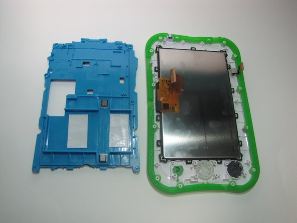
- Along the side of the blue panel are 6 screws. Unscrew each of the screws with a Phillips #1 screwdriver.
- Remove the panel and the remainder of its contents and set aside.
- The screen is now exposed and can be removed and replaced.