ASUS Eee Pad Transformer Motherboard Replacement
ID: 115713
Description: The motherboard is one of the most important...
Steps:
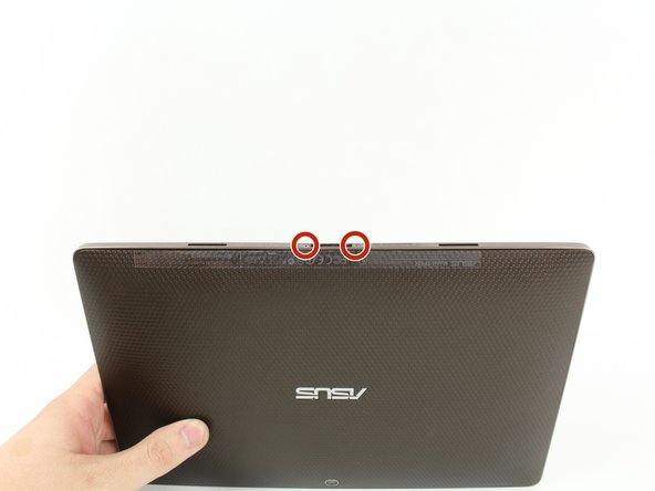
- Use T5 Torx Screwdriver to remove two 4.5 millimeter T5 screws on either side of the port on the bottom of the tablet.
- Use the Plastic Opening Tool to pry between the main tablet body and the outer rim casing. Remove the outer rim casing by prying all the way around the device and pulling the rim upward.
- The physical buttons are located on the outside of the rim on the right side, proceed with the guide to locate internal buttons.
- Remove the four 2 millimeter Phillips #00 screws at the corners of the tablet.
- Use a Phillips #00 Screwdriver to remove the three 3 millimeter screws securing the front panel to the back panel found above the camera area, on the top portion of the tablet.
- Use a Phillips #00 Screwdriver to remove the three 3 millimeter screws securing the front panel to the back panel found on the bottom portion of the tablet near the port.
- Remove back panel by pulling away from the remaining device.
- Use Phillips #00 Screwdriver to remove four 3 millimeter screws found on the metal panel.
- Metal panel is glued to the battery. Remove with care.
- Use Plastic Opening Tool to pry off the metal panel from the battery starting on the right side corners and working around the rest of the panel.
- Do NOT pry the battery connector upward as shown in this photo. Instead, pull the connector straight out (in the direction of the wires).
- Battery is glued to device. Remove with care.
- Peel off tape from around the edges of the battery.
- Insert Plastic Opening Tool into slot on side of battery found near the wire bundle.
- Lift up the battery off of the device.
- Use a Phillips #00 Screwdriver to remove the six 3 millimeter screws securing the motherboard to the screen.
- Detach the Wifi and GPS antennas (three coaxial cables connected to the motherboard) using hands,metal spudger, or tweezers by lifting away from the device.
- Use fingers, plastic opening tool, or metal spudger to lift the clips to the ZIF connector. Remove the ribbon cables attached underneath.
- Remove any tape that is holding down any free wires.
- Carefully lift the motherboard and slide it out from underneath its constraints.
- Unclip the ribbon cable from the ZIF connector using a plastic opening tool or metal spudger.
- Remove any taped on accessories