Welding technique: How to replace the joystick potentiometer
ID: 117610
Description: Desoldering technique with [gootwitck mesh],...
Steps:
- Remove the battery pack cover.
- Remove batteries.
- We recommend using a nylon spudger for this step. A metal spudger is shown.
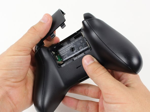
- Grip the controller firmly to remove the side handles, wedging a spudger into the seam between the front and handle plates.
- Pry the side plate away from the front plate by moving the spudger back and forth. You will need to do this all the way around the side plate's seam.
- There is a hidden screw located in the middle of the controller behind the label.
- Use a screwdriver and punch a hole directly in the center of the label.
- You may also lift the label if you do not want to puncture it.
- Remove the five 10mm screws located on the back of the controller using the TR8 Security Torx Screwdriver.
- Remove the backplate.
- Remove the faceplate.
- You may let the rumble motors hang freely out of their sockets.
- De-solder the soldered joints while holding the red and black wires down on the top motherboard.
- De-solder the black and gray wires that are attached to the top motherboard.
- Remove the rumble motors and set them aside.
- Be careful while using the soldering iron not to damage other components or hurt yourself.
- For information on how to solder, click here.
- Unscrew the two 7mm T6 screws located near the rumble motor sockets.
- Firmly grip sides of motherboard near the middle.
- Lift upwards while slightly wiggling the motherboard forward and backward.
- Lifting the motherboard will require some force.
- Remove the yellow tape holding the wires in place on the front of the controller.
- Unscrew the two 7mm T6 Hex screws located on underside the triggers.
- Remove the trigger covers.
- Desolder the wires from the motherboard.
- Remove the rumble motors from its socket and pull the wire with it.
- Remove the six T6 Torx screws located on the bottom motherboard.
- Remove the bumpers by prying them off of the pegs that secure them, using a spudger. They are located on the front and back of the controller.
- A standard nylon spudger is recommended for this step. Using a metal spudger near the motherboard as shown risks damaging your device.
- Lift the piece surrounding the Home button off of its pegs.
- Pry it off of the other side, using a spudger on the pins.
- A standard nylon spudger is recommended for this step. Using a metal spudger near the motherboard as shown risks damaging your device.
- Removing this piece may require a lot of force.
- Remove the bottom motherboard.