Google Pixel 2 XL Rear Camera Replacement
ID: 118142
Description: This is an outdated guide, go here for the...
Steps:
- If your display glass is cracked, tape over the glass to prevent bodily harm and further breakage. This also makes a smooth surface allowing the suction cup to bond.
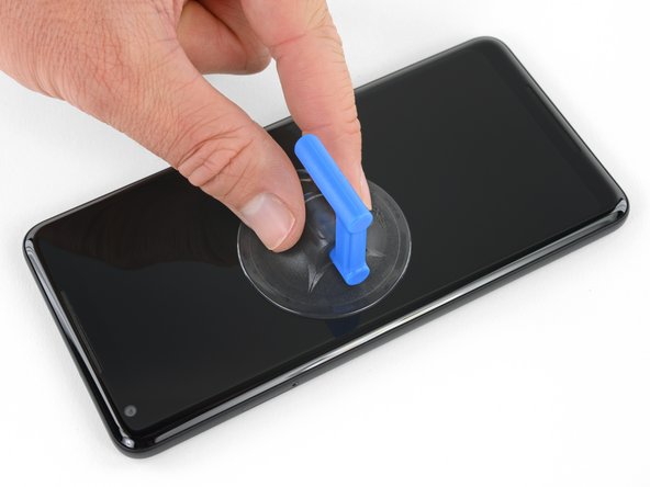
- Apply a suction cup as close to the SIM slot edge of the phone as you can while avoiding the curved edge.
- The suction cup will not make a good seal on the curved portion of the glass.
- Pull up on the suction cup with firm, constant pressure and insert an opening pick between the front panel and rear case.
- This requires a significant amount of force and patience. If you have trouble, rock the suction cup and screen to weaken the adhesive, or apply heat with an iOpener, heat gun, or hair dryer.
- In the following steps, extra caution is required in certain areas to avoid damage to the phone:
- Do not insert the pick more than 0.25 inches (6 mm) into the bottom edge of the phone. If the pick contacts the folded portion of the OLED panel, it can damage the display.
- Do not cut along the left edge; there are delicate display cables that can be damaged.
- Only make very shallow cuts in the upper left corner; prying deeply can damage the front-facing camera.
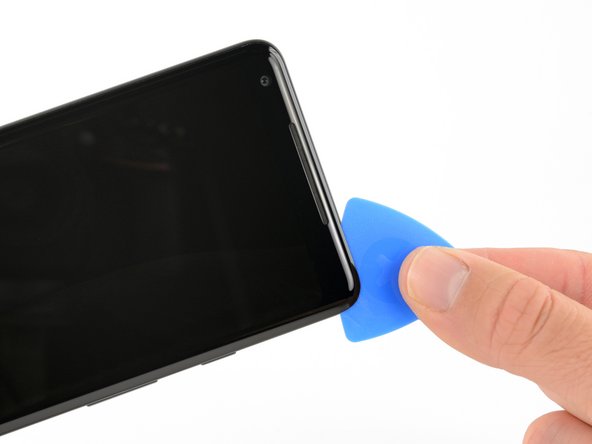
- Slide the opening pick down the right side of the phone to separate the display adhesive.
- In the following steps, use the flat edge of the opening pick, rather than a corner, to cut. This will help prevent inserting the pick too deeply.
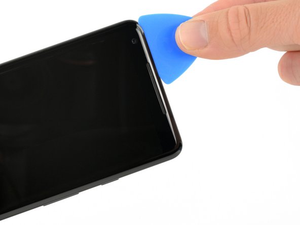
- Slide the opening pick around the lower-right corner and along the bottom edge of the phone.
- Reinsert the flat edge of the pick at the top-right corner of the phone, and slide it around the corner and the top edge of the phone.
- Gently lift the display from the right side of the phone, opening it like a book.
- If the display doesn't readily lift, do some extra prying to separate the last of the adhesive.
- Don't try to fully separate the display yet, as fragile ribbon cables still connect it to the phone's motherboard.
- Carefully lay the display flat on the table next to the rest of the phone, keeping it close to the phone to avoid straining the display and digitizer cables.
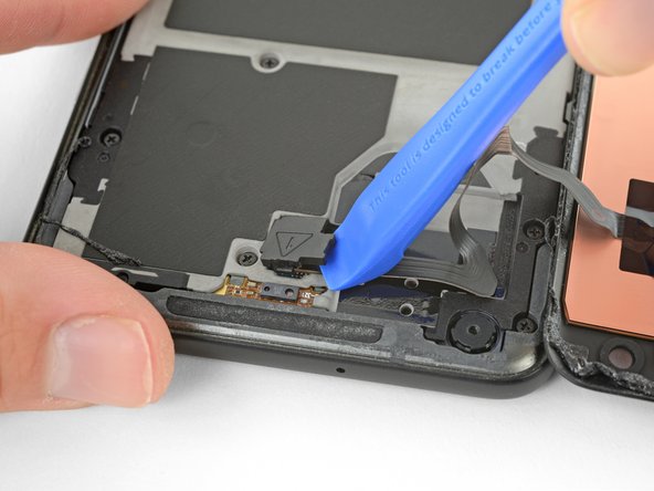
- Use the corner of an opening tool to pry up and unclip on the lower edge of the digitizer cable connector cover.
- The clip securing this cover is along the bottom edge.
- Pry carefully to avoid damaging the cable underneath, or losing the cover itself.
- Remove the connector cover.
- Make sure to keep this component so you can reinstall it during reassembly.
- Use the point of a spudger to lift the digitizer cable connector up and out of its socket on the motherboard.
- To re-attach press connectors like this one, carefully align and press down on one side until it clicks into place, then repeat on the other side. Do not press down on the middle. If the connector is misaligned, the pins can bend, causing permanent damage.
- If any part of your screen doesn't respond to touch after your repair, re-seat this connector, making sure it clicks fully into place and that there's no dust or other obstruction in the socket.
- Use tweezers to remove any tape from the display connector cover.
- Insert the point of a spudger into the small hole on the edge of the display connector cover.
- Use the spudger to pry the cover out of its recess.
- Remove the connector cover.
- Make sure to keep this component so you can reinstall it during reassembly.
- Use the flat edge of a spudger to lift the display cable connector up from its socket.
- Remove the display.
- During reassembly, pause here if you wish to replace the adhesive around the edges of the display.
- Remove eleven 3.8 mm Phillips screws securing the midframe.
- Throughout this repair, keep track of each screw and make sure it goes back exactly where it came from.
- Insert an opening tool into the notch in the midframe near the volume buttons and pry the midframe up and away from the rest of the phone.
- Remove the midframe.
- Use the flat end of a spudger to disconnect the battery connector.
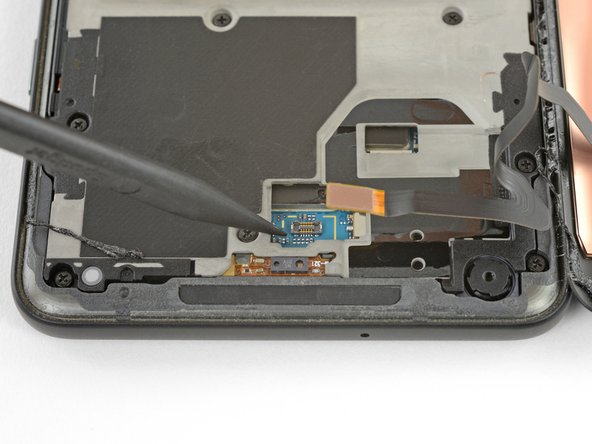
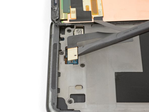
- Use tweezers to peel the black tape off of the camera connector.
- Disconnect the camera and remove it.