Motorola Moto E5 Screen Replacement
ID: 118729
Description: Follow this guide to replace a cracked or...
Steps:
- Be sure to power off your phone before you begin.
- Use a SIM eject bit, SIM eject tool, or paper clip to remove the SIM card from the phone.
- Prepare an iOpener and heat the back of the phone along one edge for about two minutes, or until it's slightly too hot to touch. This will help soften the adhesive securing the back cover to the phone.
- You may need to reheat and reapply the iOpener several times to get the phone warm enough to cut the adhesive. Follow the iOpener instructions to avoid overheating.
- A hair dryer, heat gun, or hot plate may also be used, but be careful not to overheat the phone—the internal battery is susceptible to heat damage.
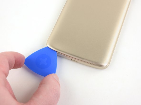
- Apply a suction handle to the back cover, near the middle of the edge you heated up.
- Pull the suction cup with firm, constant pressure to create a slight gap between the phone's frame and the back cover.
- Insert an opening pick into the gap.
- Slide the opening pick along the edge of the phone, cutting through the adhesive securing the back cover to the phone's frame.
- As you move on to cutting the adhesive around the rest of the phone, it may help to leave an opening pick in place here and grab another for the following steps.
- Use the iOpener to heat the back of the phone along its bottom edge for about two minutes, or until it's slightly too hot to touch.
- Continuing sliding the opening pick down and cut the adhesive around the bottom of the phone.
- If the adhesive is too tough to slice, continue to heat it until it softens enough to slice through it fairly easily.
- Use the iOpener to heat the back of the phone along the other edge for about two minutes, or until it's slightly too hot to touch.
- Continue cutting through the adhesive along the side of the phone.
- Use the iOpener to heat the back of the phone along its top edge for about two minutes, or until it's slightly too hot to touch.
- Continue cutting through the adhesive along the top edge of the phone.
- There are some areas around the edge that are held down with plastic clips. The opening pick should detach most of the clips. If not, insert an opening tool into the gap and pry the back cover up to release the clips.
- Once all the adhesive is cut, carefully lift the back cover off the back of the phone.
- Don't fully remove the back cover yet. The fingerprint sensor cable is still connected to the phone, and it can rip easily with too much tension.
- Remove the following Phillips screws securing the fingerprint sensor cable cover:
- One 1.6 mm screw.
- One 3.8 mm screw.
- Throughout the repair, keep track of each screw and make sure it goes back exactly where it came from to avoid damaging your phone.
- Use a pair of tweezers to remove the fingerprint sensor cable cover.
- Use a spudger to pry up and disconnect the fingerprint sensor cable connector.
- Remove the back cover.
- Since the back cover is held down with clips, replacing the adhesive around the perimeter of the back cover is optional. Replacement adhesive comes in a pre-cut sheet to match the contours of the back cover.
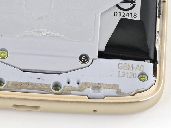
- Remove the eleven 3.8 mm-long Phillips screws securing the midframe.
- A couple of screws are hidden under "S" stickers. It may help to remove these stickers with a pair of tweezers before removing the screws.
- Insert your fingernail or the flat end of a spudger into the notch at the bottom of the midframe.
- Pry up with your fingernail or the spudger to loosen the midframe and remove it.
- Use the point of a spudger to pry up and disconnect the battery connector.
- Use a pair of tweezers to peel up the two battery adhesive tabs at the bottom of the battery.
- Be careful not to jab the battery with any sharp tools. A punctured battery may leak dangerous chemicals or catch fire.
- Slowly pull the battery adhesive tabs to release them from the bottom of the battery.
- Be sure to pull very slowly, giving the strips time to stretch and separate.
- Pull at about a 45-degree angle to prevent the strips from dragging too much on the battery or the phone's frame.
- If the adhesive strips break off, move on to the next step for an alternative battery removal method.
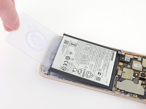
- If the adhesive strips broke and you can no longer access them, insert a plastic card in between the bottom of the battery and the phone's frame.
- Carefully push the card down and inward to wedge it underneath the battery and pry it up.
- Avoid bending the battery while you perform this step. Go slowly and be patient with the remaining adhesive.
- If you successfully removed the adhesive strips, insert the flat end of a spudger in between the bottom of the battery and the phone's frame.
- Lift up the battery to free it from its recess and remove it.
- Before installing the new battery, be sure to remove any broken adhesive strips that were left behind.
- Remove the four 3.8 mm-long Phillips screws securing the daughterboard.
- Use a spudger to pry up and disconnect the daughterboard cable connector from the daughterboard.
- Use the flat end of a spudger to pry up the daughterboard and free it from its recess.
- The daughterboard is still attached to an antenna cable, so lift the daughterboard up from the left side of the phone and flip it over its right side to prevent ripping the antenna cable out.
- Use the point of a spudger to pry up and disconnect the antenna cable connector on the motherboard.
- Use your fingers or a pair of tweezers to detach the antenna cable from its groove along the side of the phone.
- Remove the daughterboard and antenna cable.
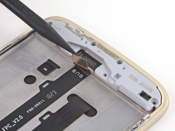
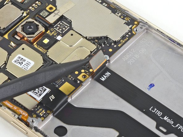
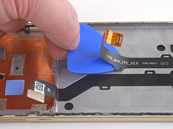
- Use the point of a spudger to pry up and disconnect the daughterboard cable from the motherboard.
- Use a spudger to pry up and disconnect the display cable from the motherboard.
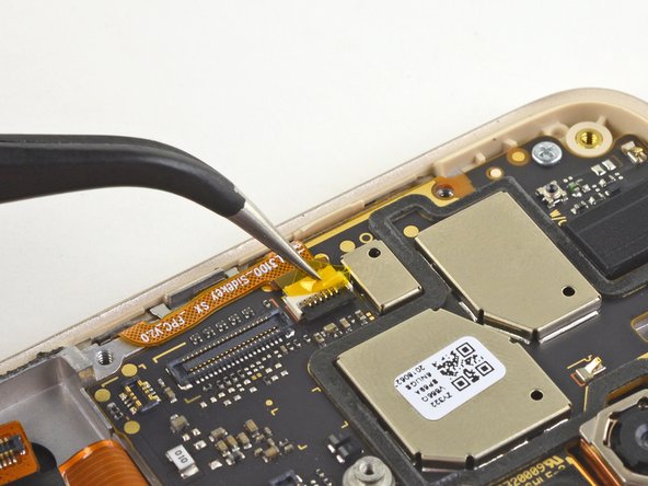
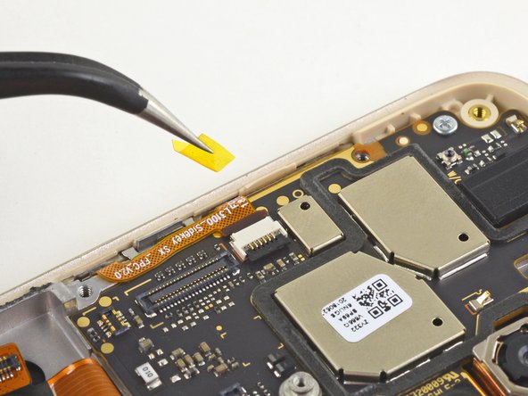
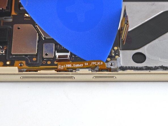
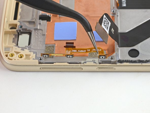
- Use a pair of tweezers to peel up and remove the tape covering the volume button connector.
- Use the point of a spudger to flip up the black locking lever on the volume button connector.
- Use a pair of tweezers to pull the volume button cable straight out of its connector.
- Slide an opening pick along the underside of the volume button cable to cut the adhesive and free it from the motherboard.
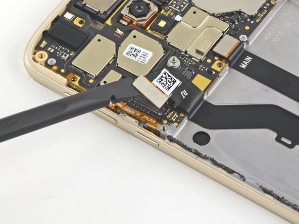
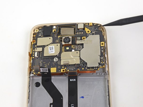
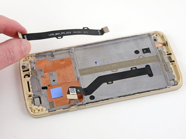
- Remove the two 2.9 mm-long Phillips screws securing the motherboard.
- Insert the point of a spudger anywhere in between the motherboard and the phone's frame.
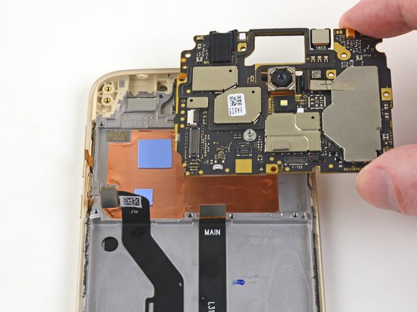
- Pry the motherboard up to free it from its recess and remove it, making sure it doesn't snag on any of the cables and connectors.
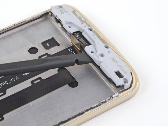
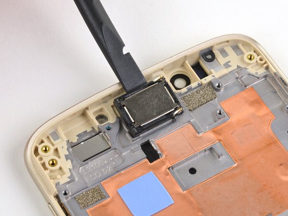
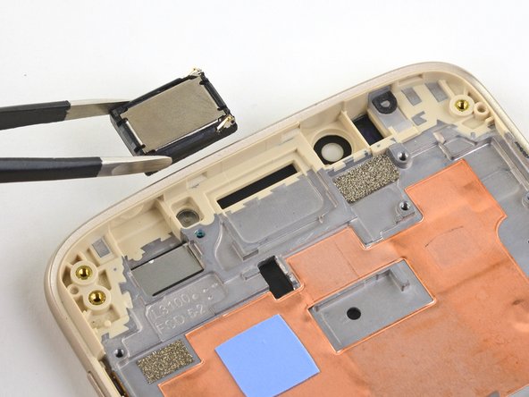
- Use the flat end of a spudger to pry up and free the earpiece speaker from its recess.
- The earpiece speaker is slightly adhered to the phone's frame, so a bit of resistance is normal.
- Use your fingers or a pair of tweezers to remove the earpiece speaker.
- During re-assembly, be sure the two spring contacts on the earpiece speaker point upward and face the right.
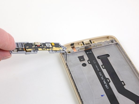
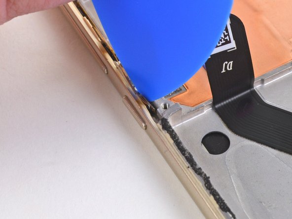
- Insert an opening pick into the gap between the volume buttons and the phone's frame.
- Slide the opening pick along the volume buttons to cut the adhesive securing it to the phone's frame.
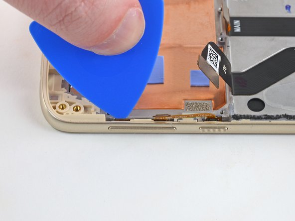
- Use a pair of tweezers to remove the volume buttons from the phone's frame.
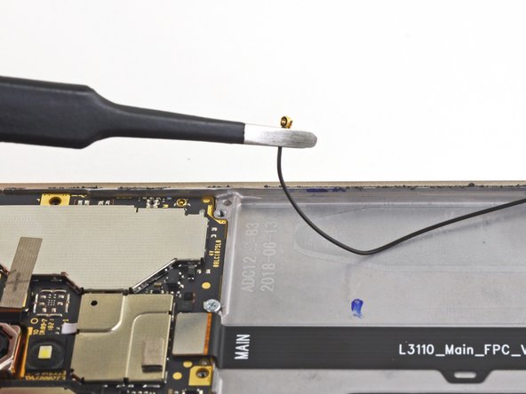
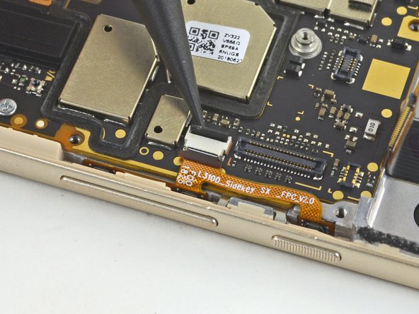
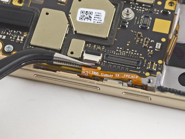
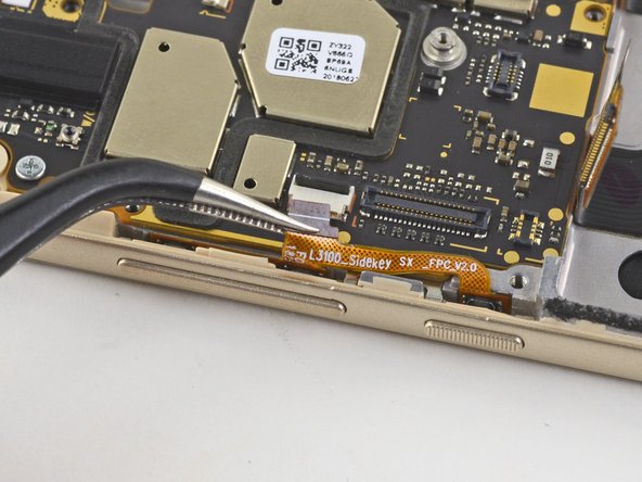
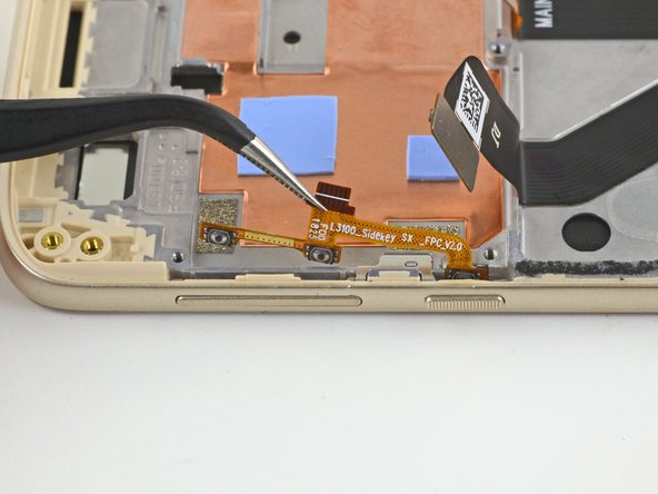
- Insert an opening pick underneath the daughterboard cable near the motherboard connector at a 45-degree angle.
- Slide the opening pick along the underside of the cable, slicing the adhesive and removing the cable from the phone.
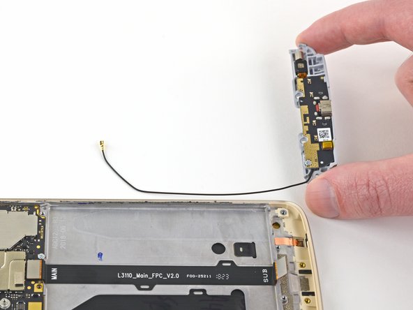
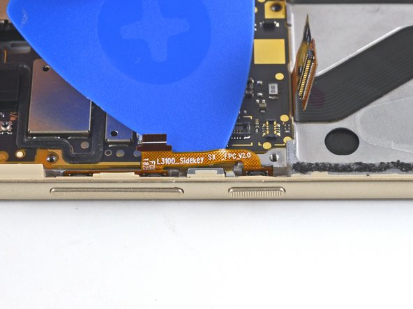
- Only the frame, the LCD screen, digitizer assembly, and display cable remain.
- Compare your new replacement part to the original part. You may need to transfer remaining components or remove adhesive backings from the new part before installing.