TI-84 Plus CE Teardown
ID: 118886
Description:
Steps:
- Remove the slide cover.
- Turn the calculator so the screen faces down.
- Take the Phillips #0 screwdriver and remove the battery cover.
- Remove the battery. (You may need to use the spudger)
- Warning: your calculator's RAM will be cleared!
- Information stored in the Archive will be safe.
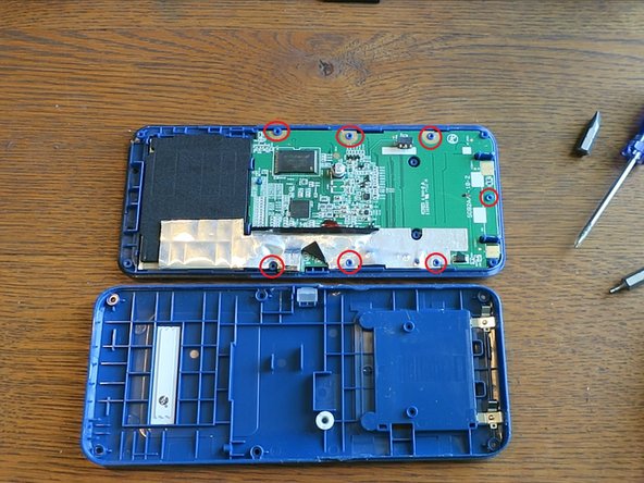
- Use the Phillips #00 screwdriver to remove the screws underneath the battery.
- Use the T6 screwdriver to remove the 6 screws on the edges of the calculator.
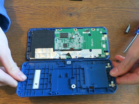
- Use a spudger to separate the top shell from the bottom one by prying the crease all around the calculator.
- The screen bezel separates easiest.
- You do NOT need to worry about keeping one side face down. The buttons will not fall out.
- The middle part is very difficult to separate! You will need to use a lot of force.
- You do NOT need to worry about tearing any cables.
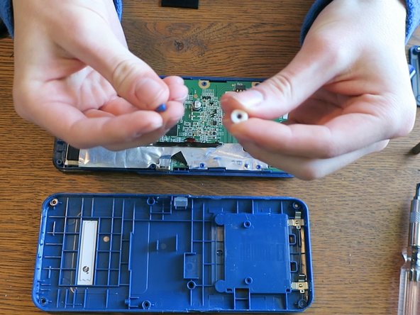
- With the back shell off, you can now access the Reset button.
- Take off the white and black rubber to access the hard plastic part.
- These are two separate pieces.
- Gently bend back the Aluminum shield. You will not be able to take all of it off since it is partially glued on.
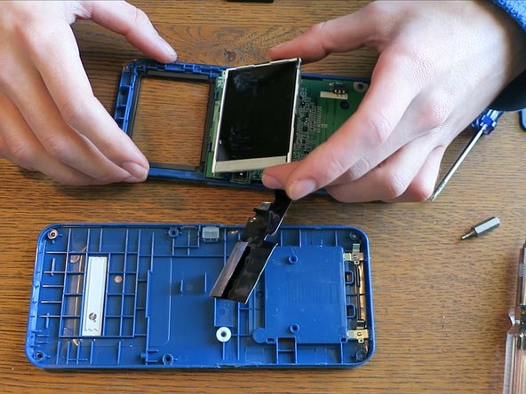
- There is some shielding wrapped around the LCD.
- If you need to access the LCD, you can pick it up and bend it back.
- Be careful not to rip the tan ribbon cable. (Which is removable)
- Follow this guide to safely disconnect the ribbon cable from the ZIF connector: Recognizing & Disconnecting Cable Connectors
- With the LCD out, you can now easily pop out the transparent, plastic cover that's connected to the shell. This allows you to replace the glue if it's weak.
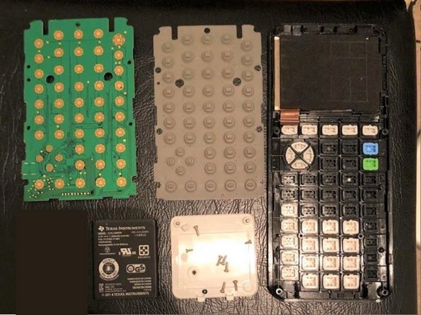
- Here are high resolution images of the front of the PCB and back of the PCB.
- Here you can see all the components of the Motherboard. Unfortunately, all the components on the PCB (except the LCD ribbon cable) are all soldered onto the motherboard.
- Unfortunately, to access the buttons underneath the motherboard you will need to break the melted bits on the PCB because it is heat-melted to the shell.
- Be sure to keep the buttons facing down otherwise they may fall out.
- Once the PCB is removed, you can now remove the grey membrane to reveal the buttons.
- I thought I'd give this an unofficial repairability score. I give it a 4. The battery is trivial to replace. The shell is (mostly) easy to remove, the LCD screen, LCD plastic cover, and the Reset button can be replaced. However, you can not upgrade anything, nor easily replace the FLASH, ASIC, USB, LED, keypad buttons and battery contacts.