Ridgid Angle Grinder R10202 Wiring Assembly Replacement
ID: 119038
Description: This guide is a step-by-step process showing...
Steps:
- Take hold of the Side Assembly Handle [8] and unscrew to detach from the grinder.
- To get to the guard, unscrew and remove the Clamp Nut [34], Grinding Wheel (not pictured) [35], and Backing Flange [36].
- To remove the Guard [38], press and hold the Guard Lever [39] and rotate the head to line up the two arrows inlayed within the metal as seen in the photograph provided.
- Once the arrows line up lift the Guard [38] from the grinder.
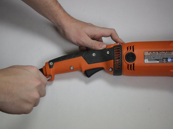
- Use TORX T20 Screwdriver to unscrew and remove 5 M5 x 16 mm, TORX Screws [28].
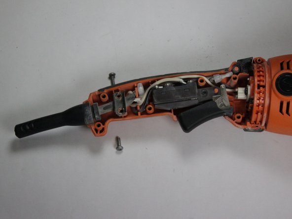
- Use TORX T20 Screwdriver to unscrew and remove 1 M5 x 28 mm, TORX Screw [1].
- Use TORX T10 Screwdriver to unscrew and remove 1 M3 x 10 mm Screw [26].
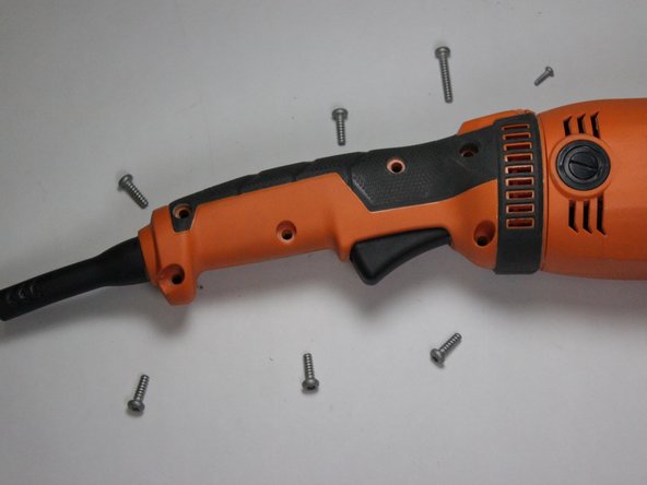
- You should now be able to separate each side of the Handle Assembly [27] as seen in the first photograph.
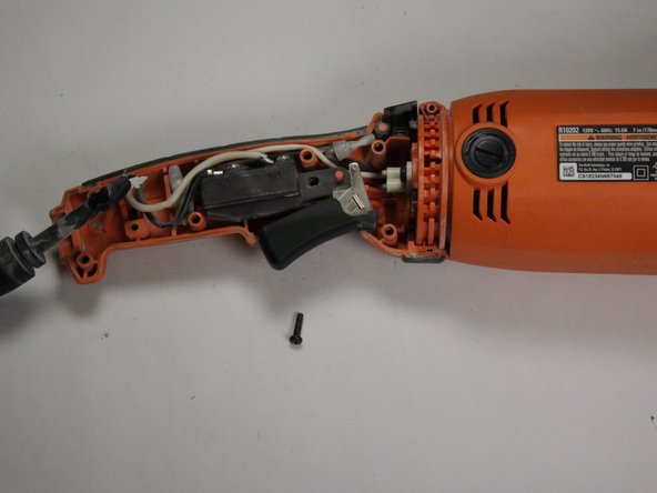
- Remove the side that should easily separate from the other.
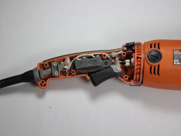
- One side will remain as seen in the second picture as it is still screwed in.
- Use a Hex Screwdriver to unscrew and remove the 2 8-16 x 1/2 in. Screws [29].
- The Cord Clamp [30] should be easily removed as seen separated from the Power Cord [32].
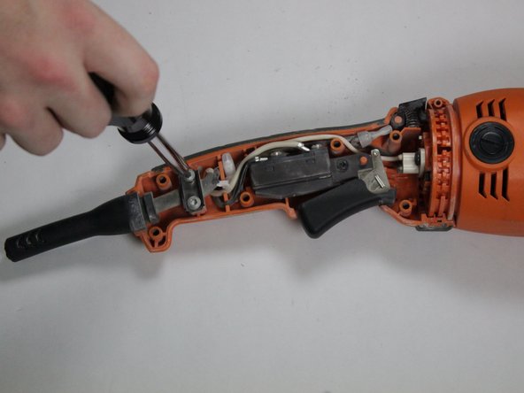
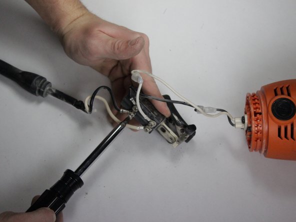
- Use a screwdriver to unscrew and remove 1 M4 x 14 mm Screw [23].
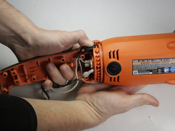
- The whole wiring assembly should be able to be lifted out of where it currently is as seen in the first photograph.
- Allow the wiring assembly to hang from the grinder as seen in the second picture.
- Press and hold the Handle Lock Button [24] to release the second side of the Handle Assembly [27].
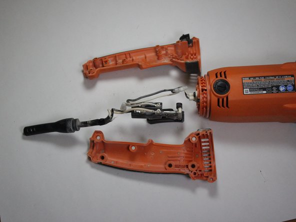
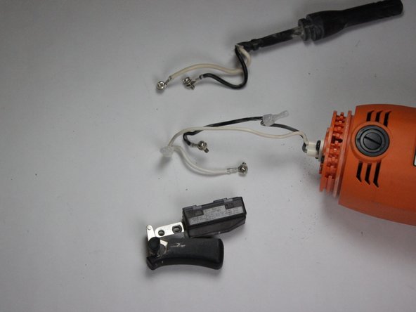
- Use screwdriver to unscrew 4 M3.5 x 7 mm Screws [22].
- The Switch [21], Power Cord [32], and Motor Housing [11] should now all be separated as seen in the third photograph.