DualShock 4 (CUH-ZCT1U) Button Circuit Membrane Replacement
ID: 121986
Description: Follow this guide to replace the button circuit...
Steps:
- Check the model number on the back of your controller. This guide was written using model CUH-ZCT1U. If you have another model, the guide procedure and replacement parts may differ slightly.
- If you have the second generation DualShock 4, model CUH-ZCT2U, use these guides.
- If you need to stabilize your controller during this repair, lay it on a soft surface such as a microfiber cloth.
- Use a Phillips screwdriver to remove the four 6.4 mm-long screws securing the rear case.
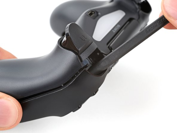
- Use an opening pick to pry each corner of the L1 button from the front case.
- Cover the button to prevent it from ejecting out of your workspace.
- Remove the button.
- Use your opening pick to pry and remove the R1 button, just as you did for the L1 button.
- Six plastic clips secure the rear case to the front case. The next four steps demonstrate how to release these clips before you can open the controller.
- Insert your opening pick at a downward angle between the front case and rear case, halfway between the handle and the action buttons.
- Slide your pick toward the handle and pry up to release the first clip.
- Repeat this procedure on the other side of the controller to release the second clip.
- Two more clips secure the rear case near the extension port and the headphone jack.
- Insert your opening pick between the front case and rear case at either side of the ports.
- Twist your pick to unclip this section of the rear case from the front case.
- If the rear case feels stuck, insert and twist your pick from different angles.
- Don't open the controller yet, as it's still held together by two very delicate clips near the triggers.
- The final two clips are very delicate, and must be disengaged from inside the controller. If you break them, don't worry—it won't affect this repair or your controllers functionality.
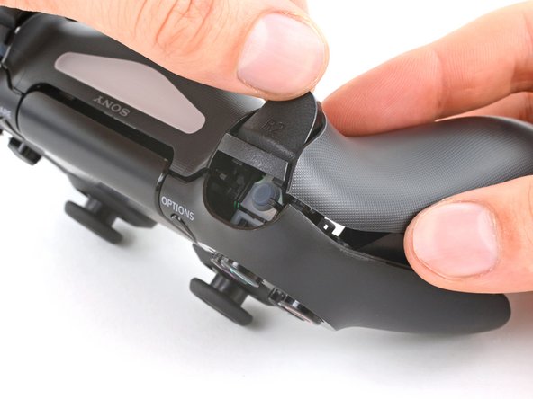
- Locate the clips by looking through the gap above the R2 or L2 buttons.
- Insert the point of a spudger through the gap above the R2 button and push the retaining clip outward.
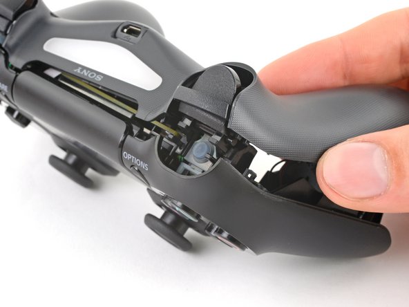
- While pushing the clip outward, slowly pull the rear case away from the front case until you feel them separate.
- Don't fully open the controller until each of the R2 and L2 clips have been disengaged.
- Repeat this procedure for the clip near the L2 button.
- Press the R2 button and slide the rear case over it.
- Press the L2 button and slide the rear case over it.
- Flip the rear case over the top of the controller and lay it down, being careful not to strain the interconnect cable.
- Use tweezers or your fingers to remove the interconnect cable by pulling its blue pull tab straight out of the socket.
- During reassembly, reconnect the cable with its blue pull tab facing the outside of the controller.
- Use tweezers or your fingers to grab and disconnect the head of the battery cable from the motherboard.
- Only pull on the head of the connector—don't pull on the cable itself.
- Remove the battery.
- Grab and remove the reset button extension from its recess in the battery bracket.
- Locate the two clips securing the battery bracket to the motherboard.
- Insert the point of your spudger into the opening behind the right bracket clip.
- Depress the clip to disengage it from the motherboard.
- Lift up the right edge of the battery bracket.
- Insert the point of your spudger in the opening behind the left bracket clip.
- Depress the clip to disengage it from the motherboard.
- Remove the battery bracket.
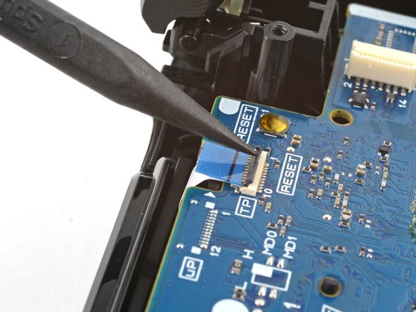
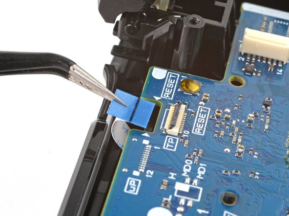
- Use the point of your spudger to flip up the locking flap securing the touch pad cable ZIF connector.
- Use tweezers or your fingers to disconnect the cable using its blue pull tab.
- Use your Phillips screwdriver to remove the 6.4 mm screw securing the motherboard.
- During reassembly, hold the motherboard tight to the front case before fastening it. Test each button to ensure the silicone button pads are properly aligned. If each button presses as expected, fasten the motherboard.
- Grab the midframe by its plastic protrusions or the vibration motors and remove it.
- Be careful not to separate the motherboard from the midframe, as they're only connected to each other by the vibration motor cables.
- During reassembly, take your time positioning the midframe. Use the alignment posts to help guide it into place, and make sure the touch pad cable doesn't become trapped underneath.
- Be careful not to strain the vibration motor cables. Follow this guide to re-solder the vibration motors if they break off the motherboard.
- Lift the motherboard and flip it over the bottom of the midframe, leaving the vibration motor cables attached.
- Firmly grip the R2 button and unclip each peg from the midframe.
- The spring may eject from the inside peg. Be careful not to lose it.
- Remove the R2 button.
- Unclip the L2 button from the midframe and remove it, making sure not to lose the small spring from the inside peg.
- During reassembly, follow these instructions to install the springs onto the R2 and L2 buttons:
- Lay the midframe face-down and orient the button properly.
- Place the spring over the inside peg with its bent ends facing upward.
- Rest one end of the spring in its channel in the button.
- Place the button over its clips and rest the other end of the spring in its channel in the midframe.
- Press the button's pegs into their clips until they snap into place.
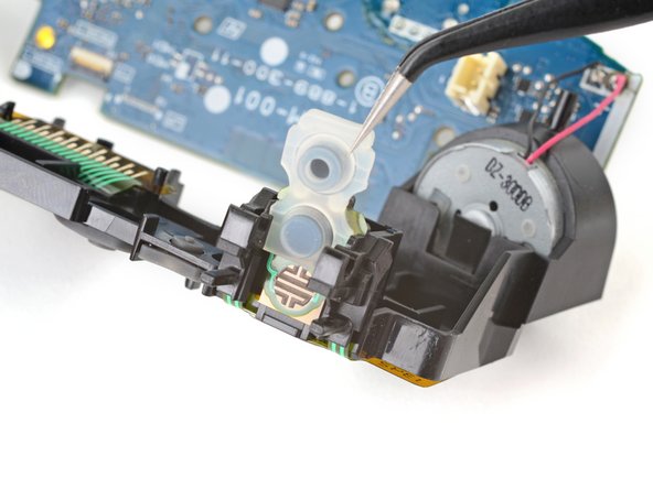
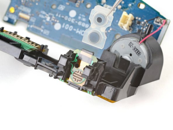
- Grab the upper edge of the R1 and R2 button pad.
- Slide the pad out of its channel in the midframe.
- Slide the L1 and L2 button pad out of its channel in the midframe and remove it.
- Each pad has two plugs and an upper groove to align it with the midframe. During reassembly, ensure the plugs are inserted in their holes and the groove is hooked onto the tab in the midframe.
- Use tweezers or the point of a spudger to lift the underside of the R1 and R2 section of the button circuit membrane.
- Slide the membrane over its retaining tab on the midframe.
- During reassembly, slide the membrane into its slot until it snaps into place over its retaining tab.
- Use tweezers or the point of a spudger to lift the underside of the L1 and L2 section of the button circuit membrane.
- Slide the membrane over its retaining tab on the midframe.
- During reassembly, slide the membrane into its slot until it snaps into place over its retaining tab.
- Peel and lift the middle section of the button circuit membrane from its retaining pegs on the back of the midframe.
- Flip the midframe over so the button circuit membrane is facing you.
- Unclip the right half of the button circuit membrane from its two retaining pegs on the face of the midframe.
- Unclip the left half of the button circuit membrane from its two retaining pegs on the face of the midframe.
- Grab each side of the button circuit membrane.
- Feed the middle section of the membrane through its cutout in the midframe.
- Remove the membrane.