Acer Chromebook C720-2827 Keyboard Replacement
ID: 122056
Description: Use this guide to replace the keyboard on your...
Steps:
- Remove the thirteen 6.0mm screws on the back panel using your Phillips #1 screwdriver.
- Pry the back panel open with the plastic opening tool.
- Remove the two 6.0mm screws securing the battery with your Phillips #1 screwdriver.
- Carefully pull out the battery wire connected to the battery port.
- Slowly lift the battery to remove it from the Chromebook.
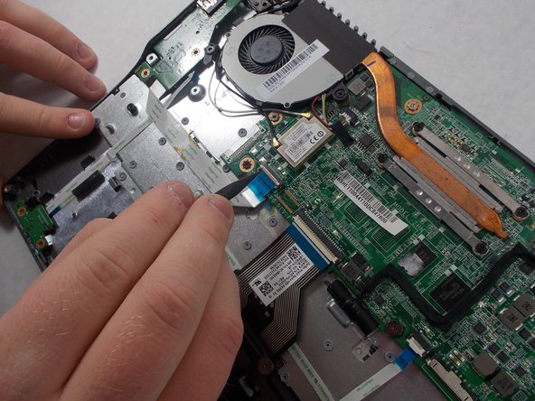
- Remove the single 3.0mm screw securing the solid state drive using a Phillips #1 screwdriver.
- Carefully pull out the solid state drive using two fingers.
- Unplug the speaker wire from the motherboard.
- Carefully pull out the speakers from each side of the Chromebook.
- Remove the three 6.0mm screws using the Phillips #1 screwdriver.
- Remove the two 3.0mm screws using the Phillips #1 screwdriver.
- Position the spudger under the switch that connects the ribbon cable to the motherboard.
- Flick the spudger up to flip the switch up.
- Pull the blue tab on the ribbon cable to remove it.
- Grab the edges of each piece of circuitry that is included with the SD Card Reader and USB Port.
- Pull each piece of circuitry out of the Chromebook and remove it from the device.
- Position the spudger under the switch.
- Flick the spudger up to flip the switch up.
- Pull on the blue tab of the ribbon cable to remove the ribbon cable.
- Repeat the previous step and this step with the other ribbon cable that is attached to the SD Card Reader/USB Port.
- Using the Phillips #1 screwdriver, remove the four 3.0mm screws.
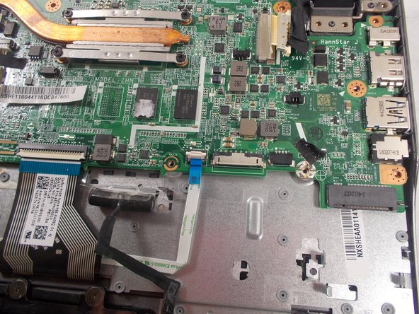
- Loosen the six 3.0mm CPU screws using the Phillips #1 screwdriver.
- The six 3.0mm CPU screws do not come out of the motherboard.
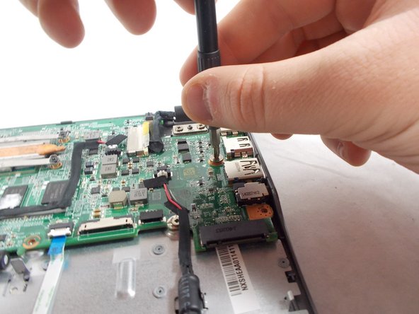
- Grab the wire for the two pin connector.
- Pull the wire to disconnect it from the motherboard.
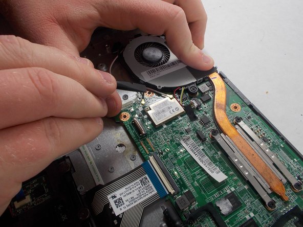
- Place the back of the spudger under the black wire that connects the wireless card to the motherboard.
- Flick the spudger up to disconnect the cable from the motherboard.
- Place the back of the spudger under the white coaxial antenna wire that connects the wireless card to the motherboard.
- Flick the spudger up to disconnect the cable from the motherboard.
- Take both wires and unravel them from the CPU fan.
- Firmly grasp the red, yellow, and white cords with two fingers.
- Pull the cords to unplug it.
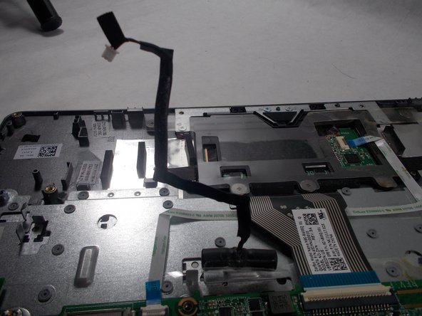
- Position the spudger under the switch of the big ribbon cable.
- Flick the spudger up to flip the switch up.
- Grab the blue tab of the ribbon cable.
- Pull on the blue tab to disconnect the ribbon cable.
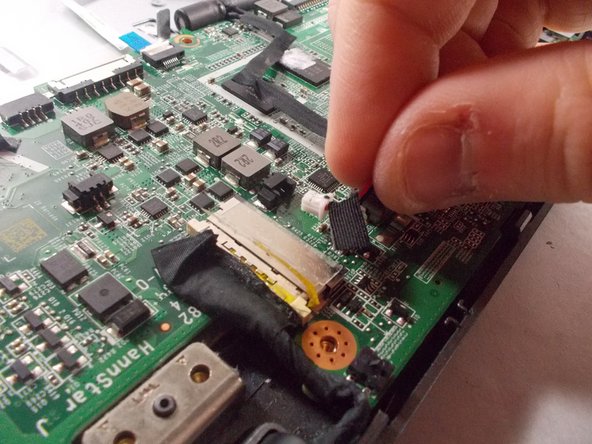
- Grab the red and black cable near the display cables, this is the cable to the other two pin connector.
- Pull on the wire to disconnect it from the motherboard.
- Flip the wire and the connector up to move it out of the way.
- Position the spudger under the switch for the smaller ribbon cable.
- Flick the spudger up to flip the smaller switch up.
- Grab the blue tab on the ribbon cable.
- Pull on the tab to disconnect the ribbon cable from the motherboard.
- Position the back of the spudger at the edge of the tape that holds the display cable in.
- Peel the tape back so it is out of the way.
- Position the back of the spudger on the display cable.
- Push the display cable out using the back of the spudger.
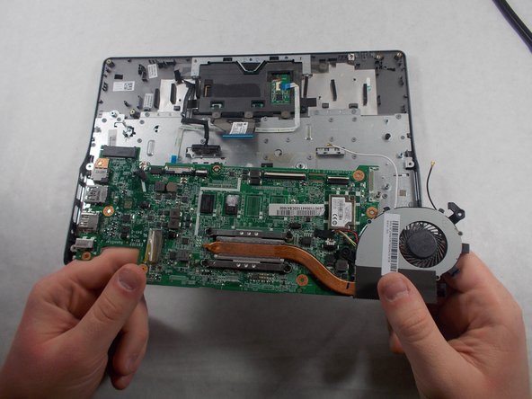
- Lift up the CPU fan to ensure that no wires are tangled. If the black and white wires are tangles please repeat step 5.
- Lift up the other end of the motherboard to completely remove the motherboard.
- Remove the two 3.7 mm screws with a Phillips #1 screwdriver.
- Remove another two 5.7mm screws with a Phillips #1 screwdriver.
- Open the laptop and separate the display from the keyboard.
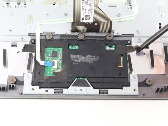
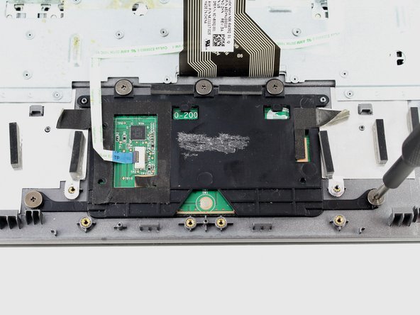
- Lift up the tape on either side of the trackpad.
- Remove four silver 2.9 mm screws with your Phillips #1 screwdriver.
- Lift the metal bracket from the case.
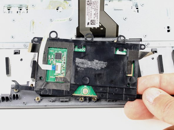
- Remove five grey 2.5 mm screws with the Phillips #1 screwdriver.
- Lift the trackpad from the case.
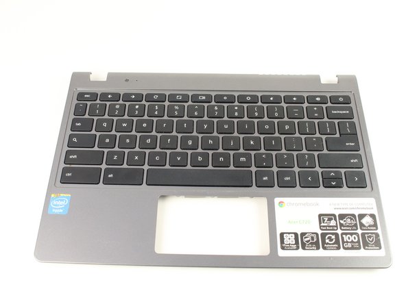
- What remains is the keyboard assembly to be replaced.