Moto C Screen Assembly Replacement
ID: 122209
Description: Use this guide to replace the screen of your...
Steps:
- Power off your phone before beginning disassembly.
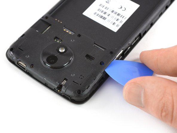
- Insert a thumbnail, or spudger, into the notch on the bottom right corner to start separating the phone unit from the back cover.
- Move it to the bottom left corner and pry the phone unit out of the back cover until you can get a good grip.
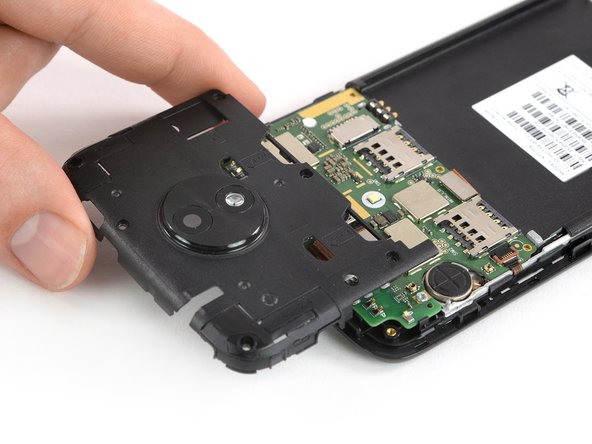
- Lift the phone out of the back cover.
- Use a finger or spudger to lever the battery out of its recess and remove it.
- Remove the six 3.5 mm long Torx T5 screws.
- Insert an opening pick between the cover and the motherboard near the SIM 2 slot where the power buttons are located.
- Slide and twist the opening pick to pry open the plastic clips securing the cover.
- Slide an opening pick between the cover and the motherboard on the opposite side next to the SD card slot.
- Twist the opening pick to pry open the plastic clips securing the cover.
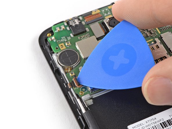
- Remove the motherboard cover.
- Remove the four 3.5 mm long Torx T5 screws.
- Some screws might be covered with stickers.
- Apply the edge of an opening pick to the bottom right corner under the daughterboard cover.
- Twist the opening pick to open the plastic clamps of the daughterboard cover.
- Slide the opening pick to the left and pry it upwards until you can get a good grip on the daughterboard cover.
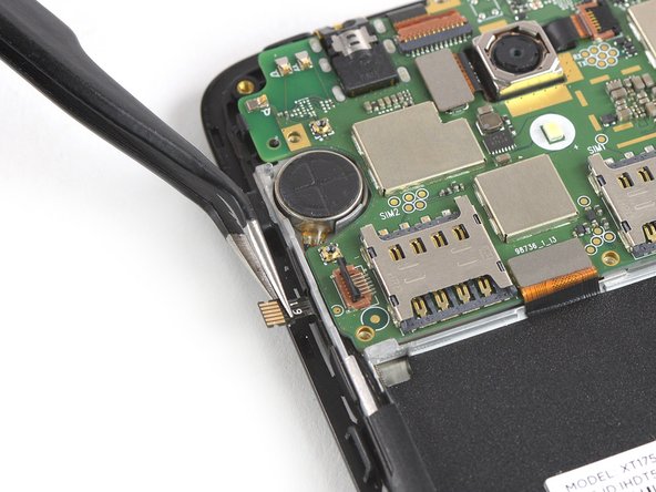
- Remove the daughterboard cover.
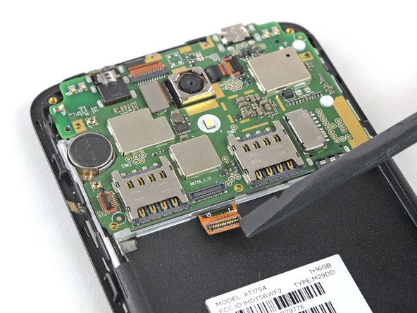
- Remove the three 2.5 mm long T5 Torx screws.
- Use the tip of an opening pick to pry up and open the black lever of the ZIF connector located on the bottom left of the motherboard.
- Use a pair of tweezers to pull the power and volume button flex cable out of the ZIF connector.
- Fold the power and volume button flex cable out of the way.
- Use the flat end of a spudger to pry up and disconnect the display flex cable located at the bottom of the motherboard.
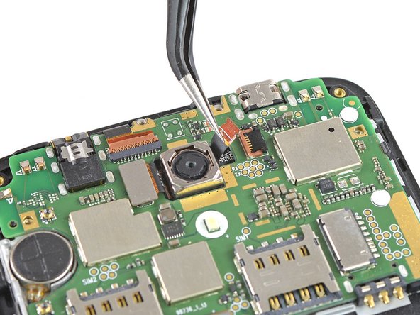
- Use the tip of an opening pick to pry up and open the black lever of the ZIF connector located at the top of the motherboard next to the rear camera.
- Use a pair of tweezers to pull the digitizer flex cable out of the ZIF connector.
- Prepare an iOpener and apply it to the upper half of the display for at least two minutes to loosen the adhesive beneath the vibration motor and the rear facing camera.
- Don't try to remove the motherboard all the way yet. The antenna cable is still connected to its rear side.
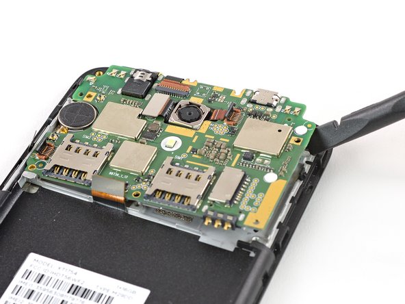
- Use a spudger to carefully lift the motherboard until you can get a good grip. Avoid to damage the cables next to the motherboard.
- Fold the motherboard over the battery cavity to access the coaxial cable connectors.
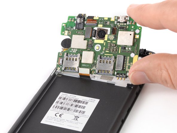
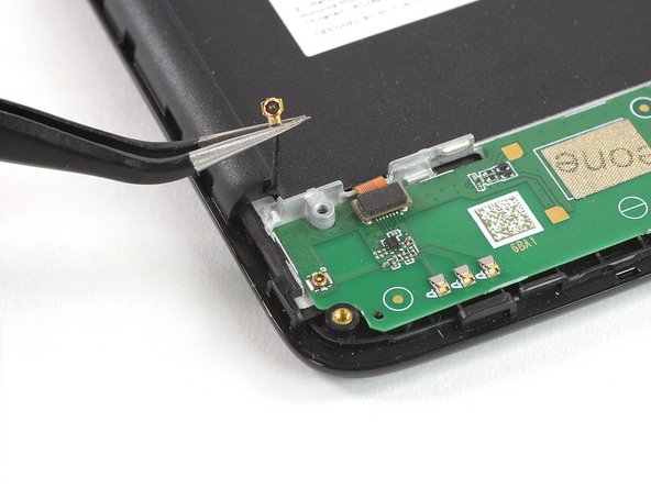
- Use a pair of tweezers to pry up and disconnect the antenna cable from the back of the motherboard.
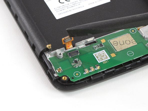
- Remove the motherboard.
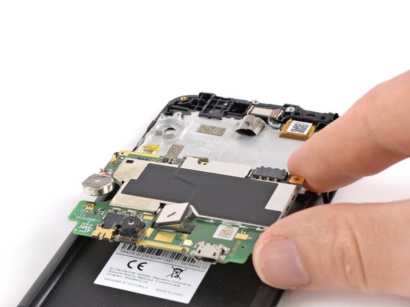
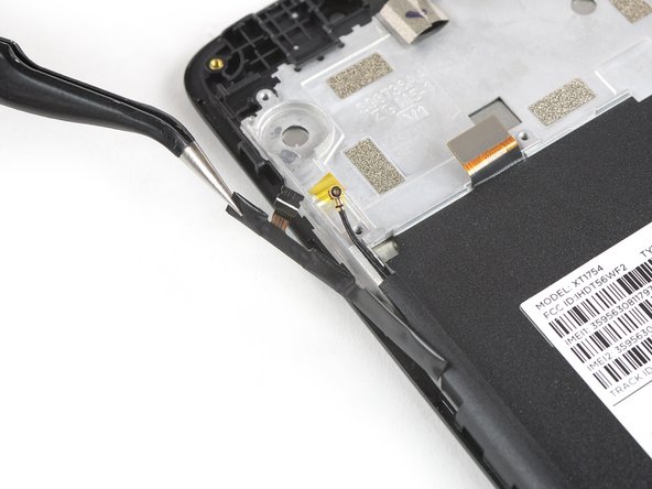
- Use a pair of tweezers to disconnect the antenna cable on the left of the daughterboard.
- Use a spudger to disconnect the digitizer flex cable on the upper left of the daughterboard.
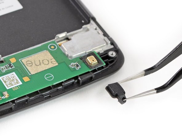
- Use a pair of tweezers to remove the rubber gasket that covers the microphone on the bottom right of the daughterboard.
- Prepare an iOpener and apply it to the bottom part of the display for at least two minutes to loosen the adhesive beneath the daughterboard.
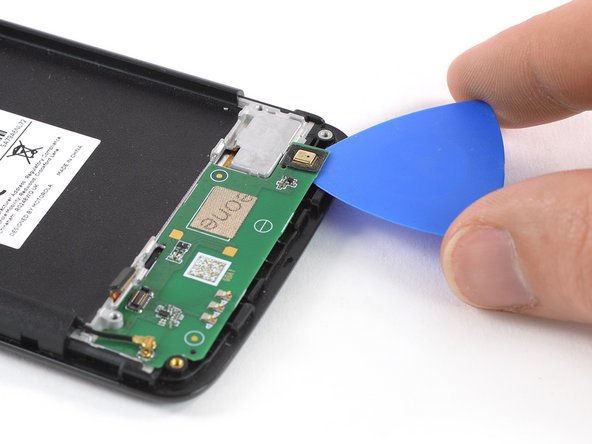
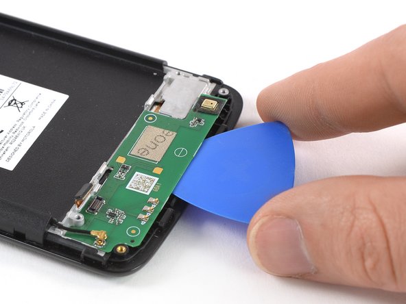
- Apply an opening pick to the bottom right corner of the daughterboard.
- Carefully slide the opening pick under the daughterboard to cut the adhesive underneath.
- Slide the opening pick from right to left to cut all the adhesive.
- Twist the opening pick to lift the daughterboard until you can get a good grip.
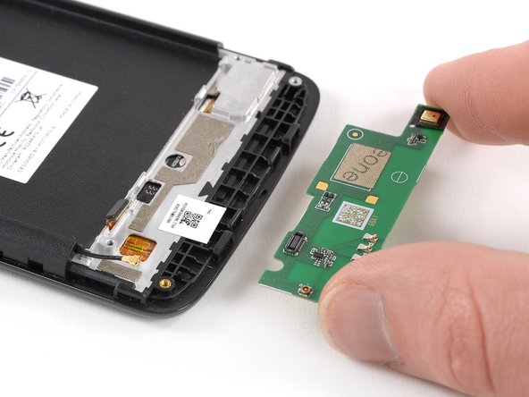
- Remove the daughterboard.
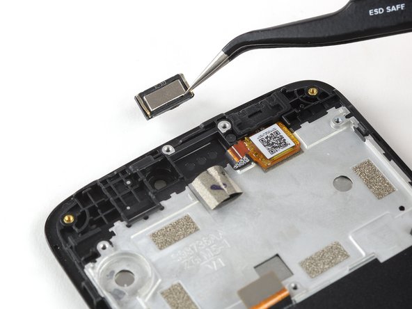
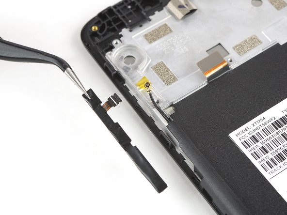
- Remove the ear piece speaker.
- When reassembling, be sure to properly orient the earpiece speaker such that the gold contacts are pointing away from the top edge.
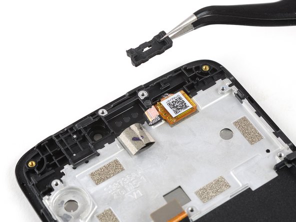
- Use a pair of tweezers to grab and remove the charging port rubber gasket.
- Use a pair of tweezers to gently peel off and remove the power and volume buttons.
- Prepare an iOpener and apply it for at least two minutes on the back of the phone to loosen the adhesive tape that sits on top of the display flex cable.
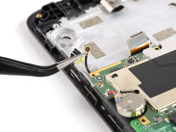
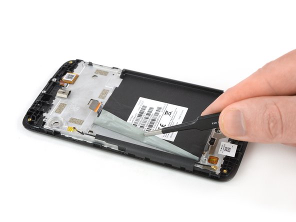
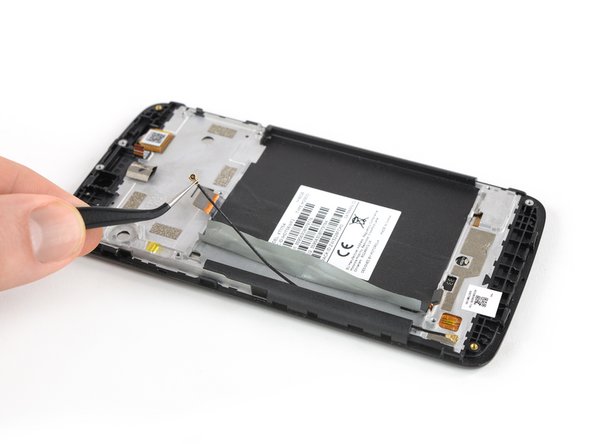
- Use a pair of tweezers to peel the adhesive tape off the left side where the antenna cable runs and fold it out of the way.
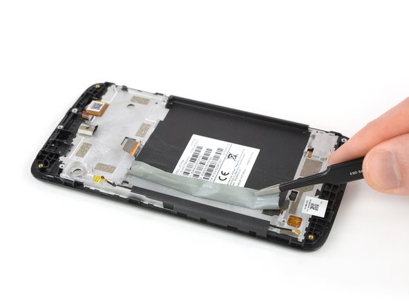
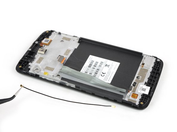
- Use a pair of tweezers to pull the antenna cable out of its routing and remove it.
- Check your replacement part for any other components that need to be transferred before reassembly.
- Maybe you also want to transfer the white label with the serial number and IMEI number on it.