HP Pavilion g7-2023cl Display Assembly Replacement
ID: 122319
Description: There are a few reasons you may want to replace...
Steps:
- Shut off your device and disconnect the power cord. Disconnect any external devices connected to the device.
- Place your finger on the battery lock slider, press toward the center of the laptop to unlock the battery.
- The lock will make a click sound letting you know that the battery is unlocked.
- Use your thumb to pry up the edge of the battery and lift it out of the device.
- When replacing the battery, align the notch on the battery with the battery lock on the device. Gently press down on the battery until you hear the lock click, which signals that the battery is secure.
- Using a Phillips #0 screwdriver, loosen the service door screw.
- This is a captive screw that will remain attached to the service door.
- Lift the service door up and away from the device.
- Locate the hard drive cable connector pull tab.
- Pinch the pull tab pulling upwards from the motherboard to disconnect the hard drive cable.
- To reconnect the cable, align it so that the cable from the connector is facing the battery and the cable lays in the groove of the base enclosure.
- Use a spudger or other ESD-safe prying tool to lift one side of the hard drive up and out of the base enclosure.
- You may be able to lift up the hard drive with just your fingers.
- Grab the end of the hard drive.
- Pull the hard drive out of the base enclosure at an angle.
- To replace the hard drive, insert it at the same angle you removed it from and slide it back into the base enclosure until it lays flat.
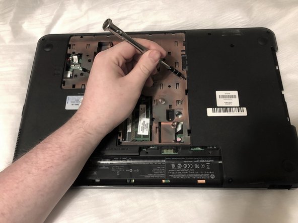
- Using a Phillips #0 screwdriver, remove the optical drive anchor screw.
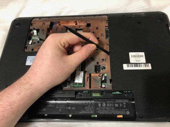
- Insert the flat end of a spudger into the optical drive release access hole.
- Orient the device so that you can remove the optical drive.
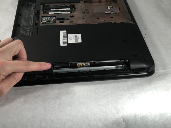
- If you are missing the bezel (face of the optical drive) or have the bezel these same steps work to remove the optical drive.
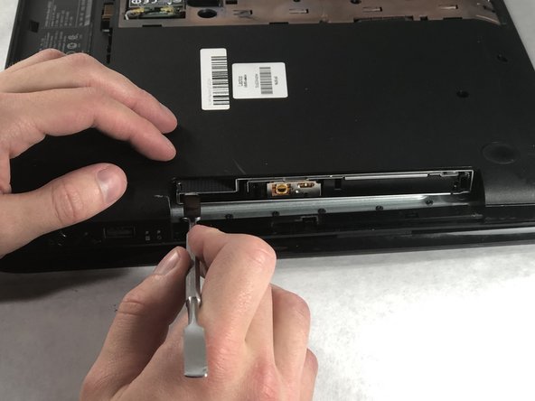
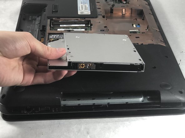
- Using a spudger, slide out the optical drive enough so that you can grab it with your hand.
- Remove the optical drive by pulling it out of the device.
- When replacing the optical drive, slide it completely back into the slot so that it fits flush.
- Locate the screw that secures the keyboard.
- It is near the RAM module and the screw hole is identified by a keyboard symbol with the text underneath it that reads M2.5×6.5.
- Using a Phillips #0 screwdriver, remove the Phillips M2.5×6.5 screw that secures the keyboard.
- Insert the pointy end of a spudger into the two keyboard release holes and press down to disengage the keyboard from the device.
- The release holes are on the base enclosure identified by a keyboard symbol with the word "release" written next to it.
- Turn the device over and open the laptop.
- Use your fingers and grab the corner(s) of the keyboard and lift up towards the display panel.
- Fold the keyboard over key side down onto the top cover so that it lays flat on the track pad.
- Locate the keyboard cable connector.
- Using a plastic opening tool, flip up the locking tab on the Zero Insertion Force (ZIF) connector.
- Pull the keyboard ribbon cable out from the connector.
- Remove the keyboard from the device.
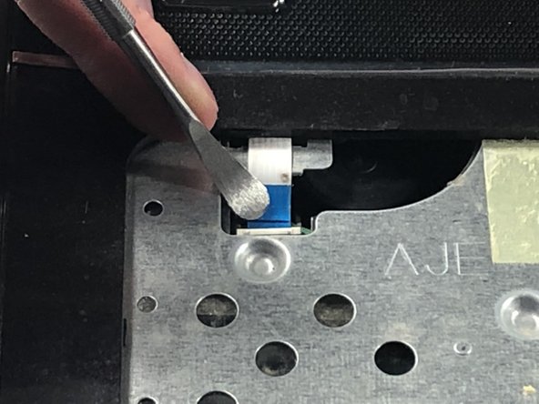
- Locate the power button cable near the top left corner of the upper case assembly.
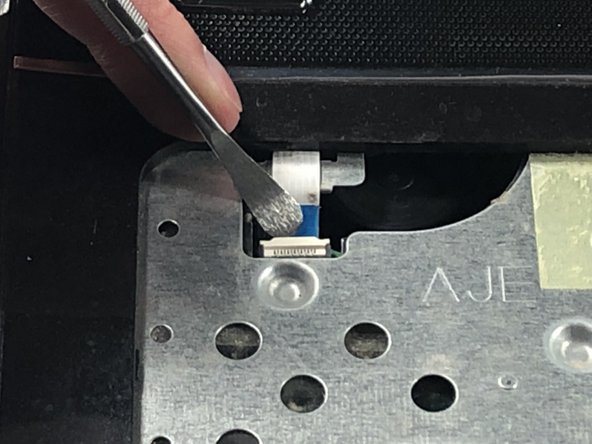
- Using a spudger, flip up the power button ribbon cable locking tab.
- Using tweezers, pull the power ribbon cable free from the connector.
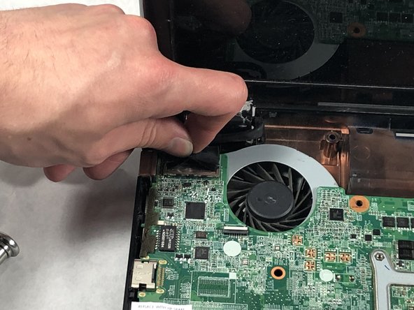
- Using tweezers or a plastic opening tool, disconnect the speaker cable from the black connector located near the right side of the laptop.
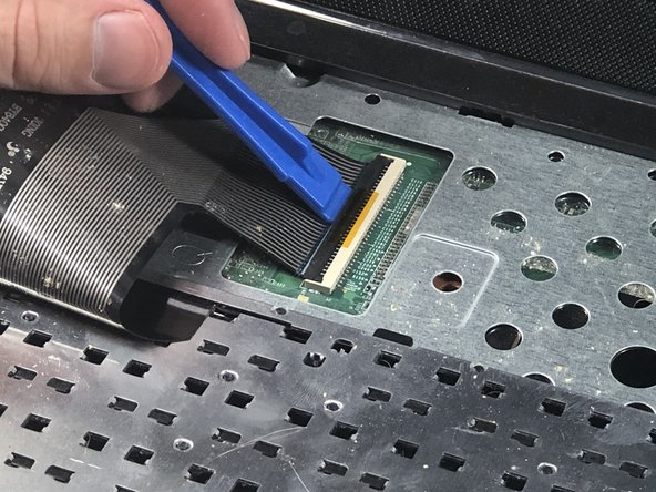
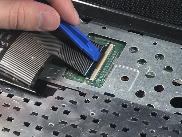
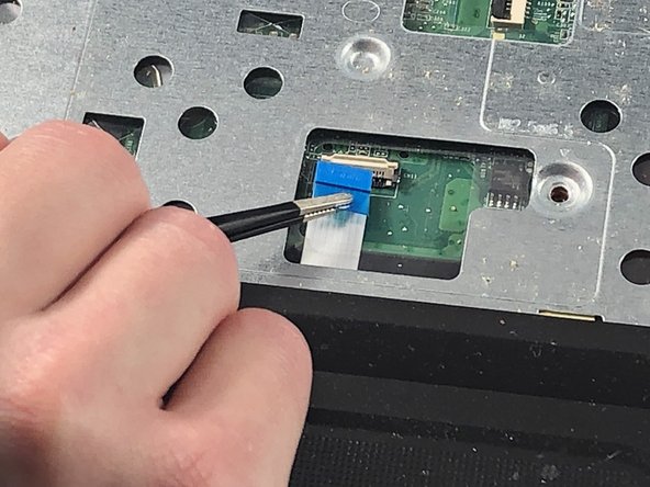
- Locate the track pad cable near the track pad.
- Using a plastic opening tool, flip up the locking tab on the Zero Insertion Force (ZIF) connector.
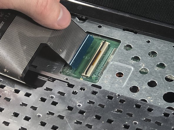
- Using tweezers, pull the trackpad ribbon cable out from the connector on the motherboard.
- Locate the three Phillips M2.5 x 6.5 on the upper case assembly.
- Remove the three Phillips M2.5 x 6.5 screws from the upper case assembly using a Phillips #0 screwdriver.
- Remove the upper case assembly by lifting it away from the rest of the laptop.
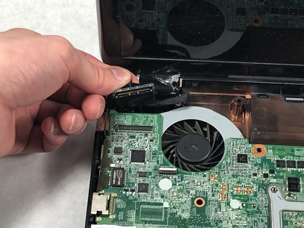
- Locate the display panel cable.
- Disconnect the display panel cable.
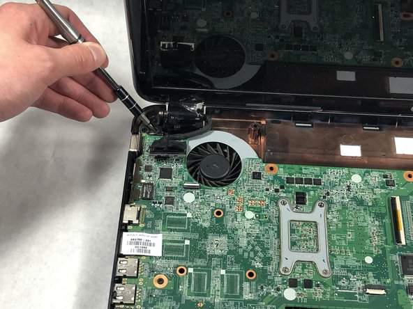
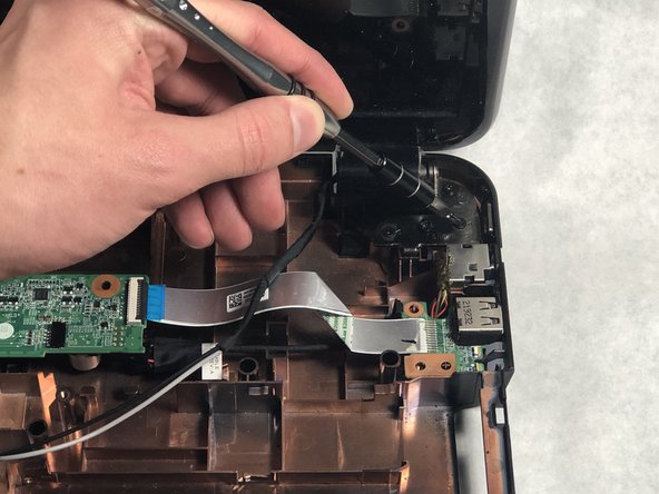
- Using a Phillips #0 screwdriver, remove all six screws securing the display assembly hinges to the laptop.
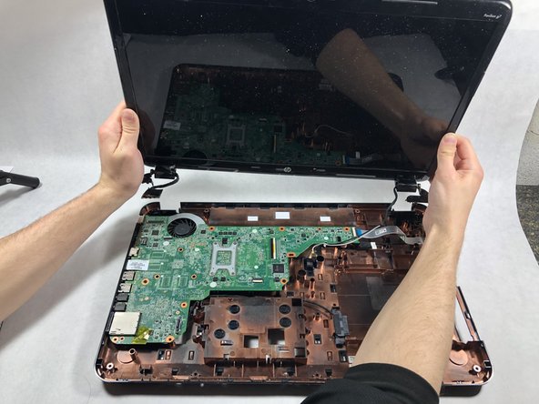
- Lift up and remove the display assembly from the laptop.