Acer Aspire V5-571-6889 Motherboard Replacement
ID: 124765
Description: This guide shows the necessary steps to replace...
Steps:
- Flip laptop over so that the back is facing upward.
- Push switch to the right.
- Pull battery away from the laptop.
- Use a #0 Phillips head screw driver to remove all of the screws.
- Flip laptop back over.
- Open the laptop.
- Wedge a prying tool between the keyboard and laptop body seam to remove keyboard.
- Be careful not to bend the keyboard too much or break the tabs that connect the keyboard to the laptop.
- Gently lift keyboard.
- Disconnect keyboard from the laptop.
- Disconnect the two ribbon cables at the near left.
- Remove six screws: ⁃ one by the left most ribbon cable connector ⁃ one mid-right center ⁃ one on the near edge left of center ⁃ three across the back
- Use a prying tool to remove the upper cover.
- Locate the hard drive.
- Lift the hard drive.
- Disconnect hard drive.
- Use #0 Phillips screw driver to remove the 2.5 x 5 mm with screw attached to the Motherboard.
- Use Tweezers to remove the antenna cables attached to the Wi-Fi card.
- Use #0 Phillips screw driver to remove the two 2.5 x 5 mm Phillips #0 screws connecting the Wi-Fi card to the Motherboard.
- Lift and pull out the Wi-Fi card.
- Use #0 Phillips screw driver to remove the 2.5 x 5 mm Phillips #0 screw on the CD-ROM Drive.
- Lift and pull out the CD-ROM Drive.
- Use #0 Phillips screw driver to remove the 2 x 3 mm Phillips #0 screw holding down CD-ROM connector.
- Pull out the CD-ROM Drive connector.
- Use Tweezers to remove the tape covering the display cable connector.
- Gently disconnect the display cable connector.
- Gently peel back the black cloth tape holding the wires in place.
- Gently lift Motherboard.
- Do not remove yet. There are some connections that need to be disconnected.
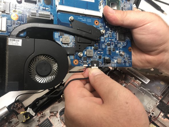
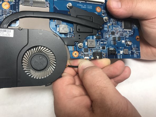
- Gently remove the connector underneath the Motherboard.
- Gently disconnect the three connectors attached to the Motherboard.
- Use #0 Philips screw driver to unscrew the three 2.5 mm x 4 mm screws connecting the CPU fan to the Motherboard.
- The motherboard is ready to be replaced.
- Attach the CPU fan to the new motherboard during reassembling.