Google Pixel 3 Rear-Facing Camera Replacement
ID: 124776
Description: This repair guide was authored by the iFixit...
Steps:
- Heat an iOpener and apply it to the bottom of the phone for one minute.
- Apply a suction cup to the heated bottom edge of the back cover.
- Make sure you did not mistake the screen side for the back cover side.
- If your back cover is badly cracked, covering it with a layer of clear packing tape may allow the suction cup to adhere.
- Lift on the suction cup with strong, steady force to create a gap.
- Depending on how aged your phone is, this may take significant force. If you are having trouble, apply more heat and try again.
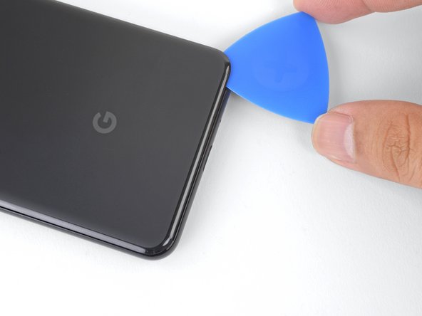
- Insert an opening pick into the gap.
- Don't use metal tools to pry, or you'll mar or shatter the glass back cover. If the panel won't budge, apply more heat, either with a hair dryer or heat gun.
- When inserting an opening pick above the power button, be careful not to insert the pick too deeply, or you will damage the fingerprint sensor cable.
- Slice the adhesive along the bottom edge of the phone and around the right corner.
- Leave a pick in the bottom edge to prevent the adhesive from re-sealing.
- Heat the right edge with an iOpener and continue slicing the adhesive with an opening pick.
- The adhesive can be very gummy. Push the pick in and out in a sawing motion to help with slicing.
- Continue heating and slicing through the rest of the phone perimeter. Leave a pick in each edge to prevent the adhesive from resealing.
- When slicing above the power button, do not insert the pick more than halfway in to avoid damaging the fingerprint sensor cable.
- Once you have sliced around the perimeter of the phone, carefully lift the left edge of the back cover.
- Do not attempt to remove the back cover. It is still attached to the phone by the fingerprint sensor cable.
- Flip the back cover along its long axis and rest it so that the fingerprint sensor cable is not strained.
- Remove the two 4.1 mm-long Phillips screws securing the fingerprint connector bracket.
- Throughout this repair, keep track of each screw and make sure it goes back exactly where it came from.
- During reassembly, be careful not to over-tighten these screws, or you may damage your display.
- Use the point of a spudger to slide the fingerprint connector bracket out from under the NFC coil.
- Remove the fingerprint connector bracket.
- Use the point of a spudger to pry up and disconnect the fingerprint connector from its socket.
- When you disconnect connectors like these, be careful not to dislodge the small surface-mounted components surrounding the socket.
- To re-attach press connectors like this one, carefully align and press down on one side until it clicks into place, then repeat on the other side. Do not press down on the middle. If the connector is misaligned, the pins can bend, causing permanent damage.
- Remove the back cover.
- Before you install a replacement back cover, be sure to remove all adhesive residue from the phone frame. Use an opening tool to scrape and high concentration isopropyl alcohol to clean the surface.
- If you are re-using the back cover, be sure to clean off any adhesive, and apply new back cover adhesive.
- If you are installing a replacement back cover, be sure to compare it with the original part. Transfer any remaining parts (such as the flash diffuser) over to your replacement part.
- Follow this guide to correctly apply new back cover adhesive.
- Remove the five Phillips screws securing the wireless charging coil:
- Two 1.9 mm screws
- Two 4.2 mm screws
- One 4.3 mm screw
- Lift up and remove the wireless charging coil.
- Use the point of a spudger to pry up and disconnect the battery press connector from its socket near the right edge of the phone.
- Remove the two screws securing the camera bracket:
- One 4.1 mm Phillips screw
- One 4 mm standoff screw
- Standoff screws are best removed using a standoff bit. In a pinch, a small flathead screwdriver will do the job—but use extra caution to ensure it doesn't slip and damage surrounding components.
- Remove the camera bracket.
- If you are replacing front-facing cameras, determine which one you need to replace:
- Normal view camera
- Wide-angle camera
- If you are doing the motherboard removal procedure, you will need to remove both cameras.
- Use the point of a spudger to pry up and disconnect the connector for the camera(s) you are replacing.
- The cameras are held in place with adhesive.
- Insert the point of a spudger behind the edge of the camera module and pry up to loosen it from the frame.
- Use a pair of blunt nose tweezers to remove the camera(s).
- If the adhesive holding the camera module is in good condition, you can re-use the adhesive. Otherwise, replace the adhesive with double-sided Tesa tape.
- When installing a replacement camera module, make sure that the phone frame lens are free of adhesive residue or debris.
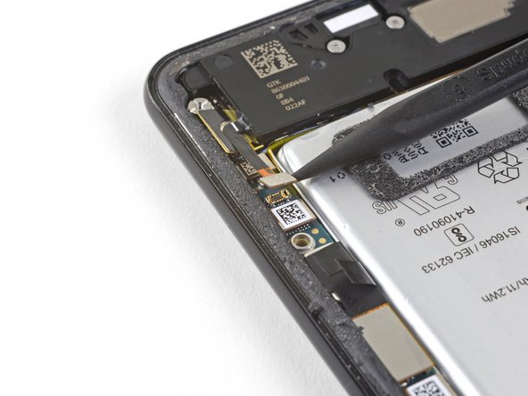
- Use the point of a spudger to pry up and disconnect the loudspeaker connector from its motherboard socket near the right edge of the phone.
- Be careful not to puncture the battery with the spudger.
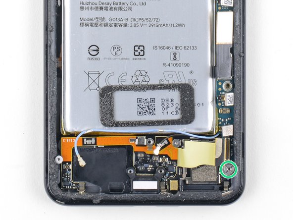
- Remove the following four Phillips screws:
- One 1.9 mm screw
- One 4.3 mm screw
- Two 4.3 mm screws with thinner shanks
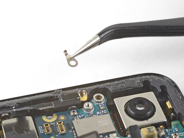
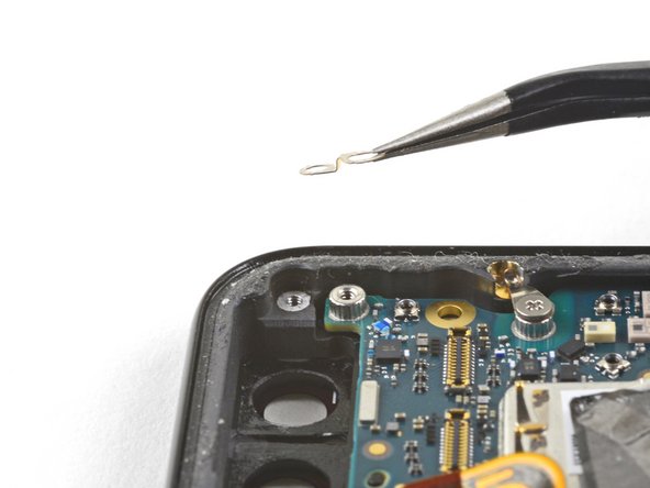
- Remove the tiny grounding clip from the left screw hole. Be careful not to lose it.
- The grounding clip installs such that the contoured edge faces the left side of the phone.
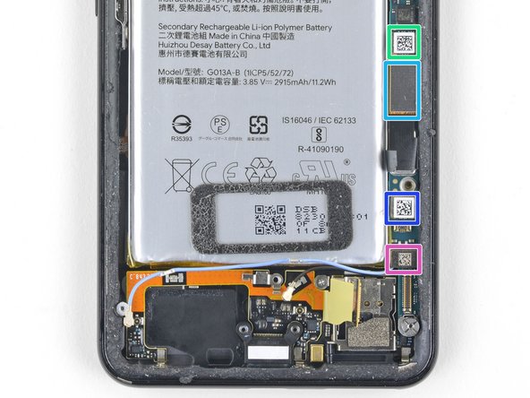
- Remove the small plastic insert from the right side of the USB-C port.
- Be sure to reinstall this insert before you screw down the daughterboard.
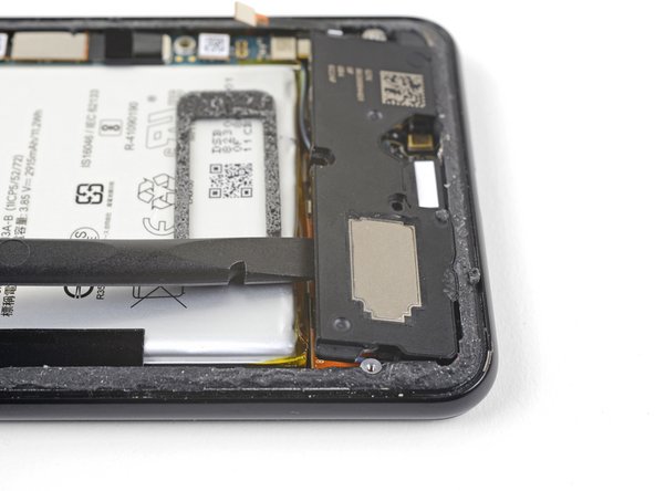
- The loudspeaker is still held in place by a strong adhesive gasket. Before attempting to remove it, pry it up in a few different places to break the adhesive seal.
- Insert the point of a spudger under the bottom right corner of the loudspeaker.
- Pry up to loosen the loudspeaker from the phone.
- Insert the point of a spudger under the top left corner of the loudspeaker.
- Be careful not to puncture the battery with the spudger.
- Pry up to loosen the loudspeaker.
- Insert the flat end of the spudger under the top edge of the loudspeaker, towards the left edge.
- Pry up to loosen the loudspeaker.
- Remove the loudspeaker.
- Before you install a replacement loudspeaker, check the adhesive gasket.
- If it is in good condition, you can re-use the gasket. Make sure that the gasket does not cover the exit hole.
- If the gasket is pulled out of place, remove it and replace the adhesive with a pre-cut strip or Tesa tape.
- Use the point of a spudger to pry up and disconnect the charging assembly's connector from its motherboard socket, near the right edge of the phone.
- Use the flat end of a spudger to carefully pry up the black tape holding the display flex cable in place, near the right edge of the phone.
- Do not use metal tools to pry, or you may damage the flex cable.
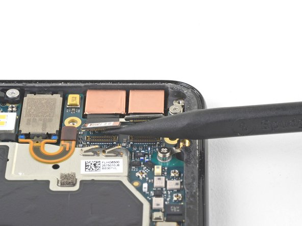
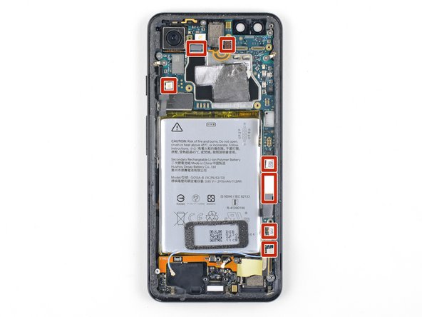
- Use a spudger to pry up and disconnect the following seven press-fit connectors from their motherboard sockets:
- External buttons connector
- Top microphone connector
- Earpiece connector
- Left squeeze sensor connector
- Screen connector
- Right squeeze sensor connector
- SIM tray connector
- Use the flat of a spudger to carefully bend the earpiece speaker's flex cable upwards, out of the way of the motherboard.
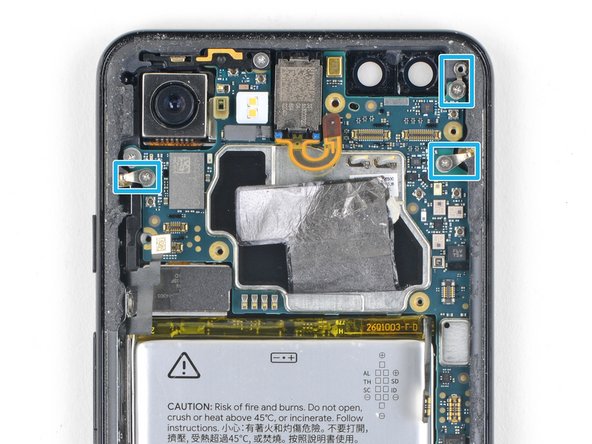
- Some of these screws hold very small grounding clips in place. Be careful not to lose these clips as you remove the screws.
- Remove the six screws securing the motherboard in place:
- One 4.2 mm Phillips screw
- Three 1.9 mm Phillips screws
- One 4.3 mm Phillips screw
- One 3.83 mm standoff screw
- Standoff screws are best removed using a standoff bit. In a pinch, a small flathead screwdriver will do the job—but use extra caution to ensure it doesn't slip and damage surrounding components.
- Remove and retain the three small metal grounding clips.
- Carefully remove the antenna bracket from the top left edge of the phone.
- To reinstall the small metal grounding clips:
- Orient the clips such that the silver side is facing upwards.
- The teardrop shaped clips should have their points facing towards the phone edge.
- The double-holed clip dips downwards towards the frame's top-right screw hole.
- Insert the point of a spudger near the top left corner of the motherboard, right below the rear-facing camera.
- Pry up gently to loosen the motherboard, bending all flex cables away to accommodate for the movement.
- If the motherboard feels firmly seated, check for any still-connected flex cables or screws.
- Insert the spudger underneath the top edge of the motherboard and carefully pry up to loosen the motherboard.
- The earpiece speaker's flex cable will press tightly against the motherboard. Take your time and carefully guide the motherboard around the flex cable.
- Lift the left edge of the motherboard and carefully swing upwards towards the right. Carefully push any press connectors snagging the motherboard out of the way.
- Do not attempt to fully remove the motherboard. It is still attached to the frame with some antenna cables.
- When you reinstall the motherboard, be careful not to trap any flex cable connectors underneath it.
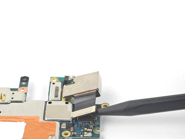
- Use the point of a spudger to pry up and disconnect the rear-facing camera connector from its motherboard socket.
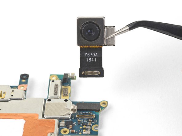
- Lift the camera module away from the motherboard, peeling the adhesive in the process.
- Remove the rear-facing camera.