Sony α6000 Motherboard Replacement
ID: 124789
Description: A motherboard is a printed circuit board...
Steps:
- Begin by placing the camera facing upside down.
- Slide the notched locking bar on the battery compartment from LOCK to OPEN.
- Push the small blue bar horizontally off of the battery.
- Remove the battery.
- Remove the 1.75mm Phillips #00 screw from the left side of the camera.
- Remove the two 1.75mm Phillips #00 screws from inside the battery department.
- Remove the 1.75mm screw using a Phillips #00 head from underneath the flash.
- Carefully remove the ribbon of the flash from the socket by using a pair of tweezers.
- The best known method to removing the ribbon is to use a pair of tweezers with a rubber tip. This will help to prevent damage to the ribbon.
- The top of the camera will be free and can be removed.
- Set the top of the camera to the side.
- Remove the three 1.75mm Phillips #00 screws just below the eye sensor.
- Remove the 1.75mm Phillips #00 screw from underneath the SD card cover.
- Remove two 1.75mm Phillips #00 screws from the bottom of the camera.
- Remove the 1.25mm screw from the right side underneath the battery cover.
- Remove the 1.75mm Phillips #00 screw just to the right of the eye sensor.
- Set the eye sensor aside.
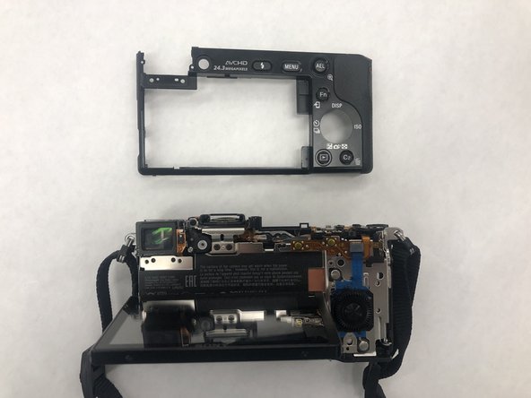
- Remove the back panel of the camera.
- Remove the two 1.25mm Phillips #00 screws near the top of the camera, just to the left of the eye socket.
- Remove the two 1.75mm Phillips #00 screws from the bottom of the camera.
- Remove the three 1.75mm Phillips #00 screws from the right side of the camera.
- Remove one ribbon that is attached to the selector wheel with a pair of tweezers.
- lift up the protector plate and remove one ribbon that is attached to the LCD screen with a pair of tweezers.
- Detach the LCD screen from the back portion of the camera and set it aside.
- Lift up the black cover to reveal the motherboard and ten ribbons.
- Use a pair of tweezers to gently pull the ribbon cables out of their sockets on the motherboard.
- Remove the four 1.25mm Phillips #00 screws located on the borders of the motherboard.
- Remove the power supply at the bottom right hand corner with a pair of tweezers.
- Lift the motherboard up and remove the last ribbon cable with a pair of tweezers.
- Remove the motherboard and set aside.