Autosampler Node Assembly (For New Version)
ID: 124811
Description: This is the new autosampler node prototype. It...
Steps:
- 1. Obtain a 6-pin amphenol connector.
- 2. Loosen the screws with a small Phillips head screwdriver.
- 3. Disassemble the 6-pin amphenol connector.
- 4. Cut two feet of 4-22 AWG stranded copper wire (red, white, black, green insulated wires) and two feet of 2-16 AWG stranded copper wire (red, black). Thread both through the 6-pin amphenol connector casing.
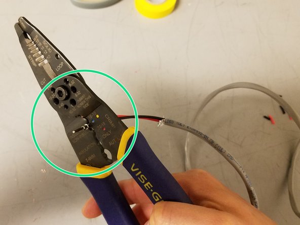
- 5. Strip 2 inches of the grey insulation off both ends.
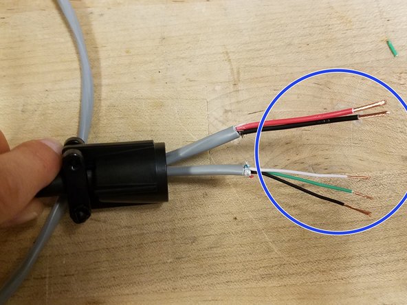
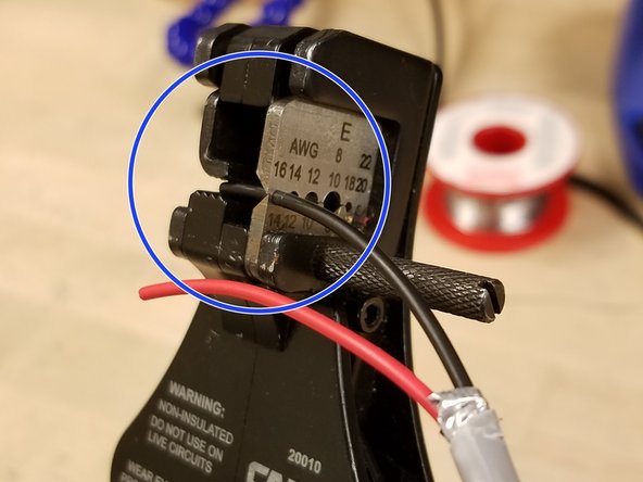
- 6. Strip 1/4" of the color insulation off each of the wires on both sides.
- Trim off the thin red wire bundled with the thin green, white and black wires.
- 7. This is what the stripped wires look like.
- 8. Insert the wires into the grey foam part of the 6-pin amphenol connector.
- 9. This is how the wires go into the grey connector.
- The top threaded screw should be placed over the grey connector before soldering.
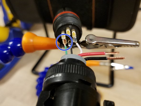
- 10. Solder the wires to the 6-pin connector. Start with the thin black wire in the bottom pin and then the white wire.
- 11. Then solder the green wire.
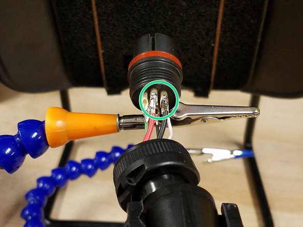
- 12. Last, solder the thicker black and red wires.
- Note: The left middle pin will not have a wire soldered to it!
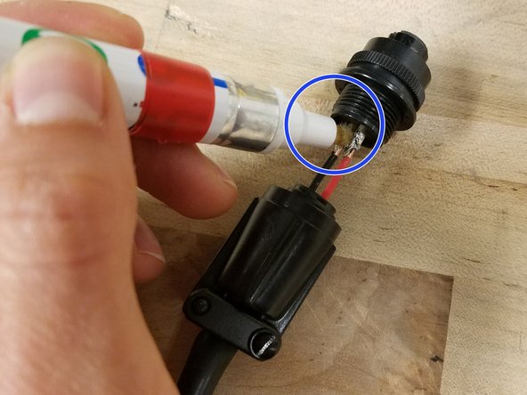
- 13. Obtain a Flux Remover Pen, 99 % Isopropyl Alcohol, and a Q-Tip.
- 14. Use the flux remover pen to remove residual flux from the soldered wires.
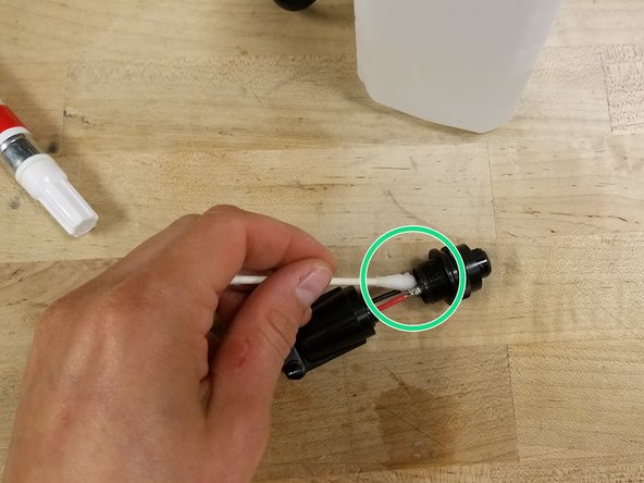
- 15. Put rubbing alcohol on the q-tip to remove excess flux remover from the soldered wires.
- 16. Cut two feet of 2-16 AWG stranded copper wire (red, black). Strip 2 inches of the grey insulation from both ends.
- 17. Strip 1/2" of each of the wires on both ends.
- 18. Place a metal contact on both the red and black wires.
- Note: You should see coper wire through the eye hole in the metal contact.
- 19. Crimp the contacts into place.
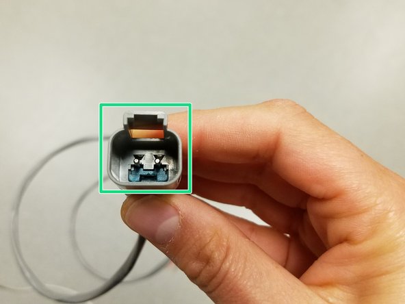
- 20. Push the metal contacts through the back end of the 2-pin amphenol connector. They will click when they are into place.
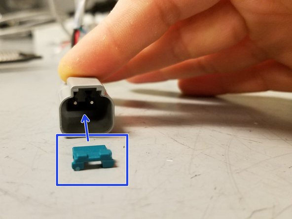
- If the opening is facing you, the red wire should be on the left and the black on the right.
- 21. The green locking piece will be inserted into the connector following this orientation.
- 22. Push the green locking piece into place. You will hear it click into place.
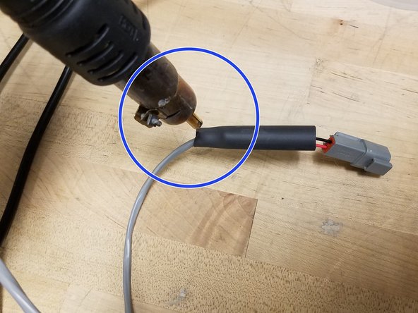
- 23. Cut two inches of heat shrink wrap And slide in on the wire to cover where the grey insulation ends.
- 24. Use a heat shrink gun to heat shrink the covering.
- 25. Measure out where the three holes should be drilled into one side of the node enclosure box.
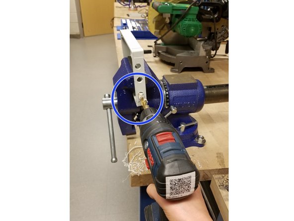
- 26. Use a 1/2" drill bit and drill three holes.
- Make sure you know how to use a drill! Ask for help if you are unsure!
- Make sure the enclosure is secure before drilling!
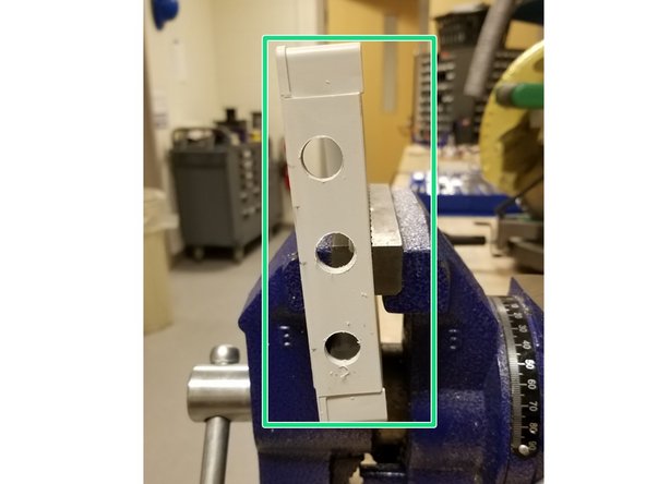
- This is what the node enclosure should look like.
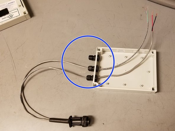
- 28. This is what a gland looks like. Connect 3 glands to the node enclosure box in the drilled holes.
- If the glands do not fit perfectly based on the location of the drilled holes, the gland's washer can be sanded or filed.
- 29. Thread the two wires from the 6-pin amphenol autosampler connector through 2 of the glands.
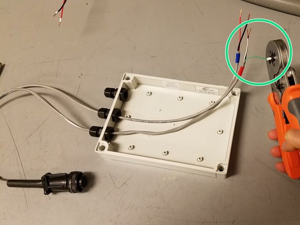
- 30. Crimp white terminals to the ends of both wires.
- 31. Thread the other end of the 2-pin battery box connector through the third gland.
- Ensure that the glands are complete before wiring the node any further, otherwise disassembly to fix a gland is difficult.
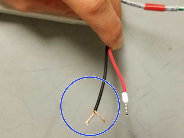
- 32. Separate about half of the copper strands from each wire.
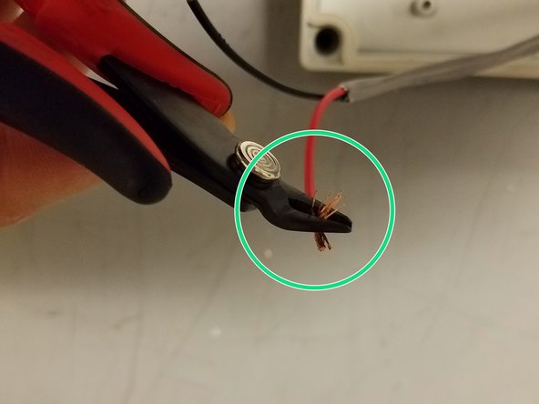
- 33. Use wire cutters to clip off the strands.
- 35. Place several pieces of the soft side of velcro into the box.
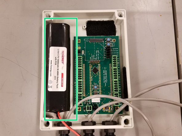
- 36. Obtain a lithium-ion 3.7V 10400 mAh 38.48Wh node battery.
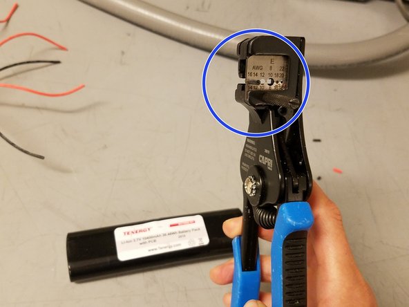
- 37. Strip 1/2" off of each wire.
- Major Warning: Ensure that that the stripped ends of the battery wires do not touch during assembly. If storing the battery after stripping the wires, insulate the ends using electrical tape.
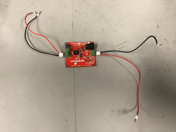
- 39. Cut four 24 AWG 6" wires. Two red and two black.
- 40. Screw them into the assigned green terminals on the Sunny Buddy solar charger.
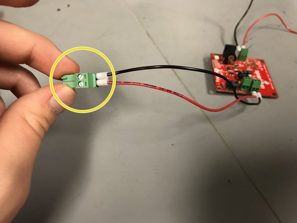
- 41. Screw the appropriate red and black wire into the pluggable header.
- 42. Obtain an Open-Storm relay board. Make sure the yellow boxed resistor is removed.
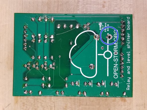
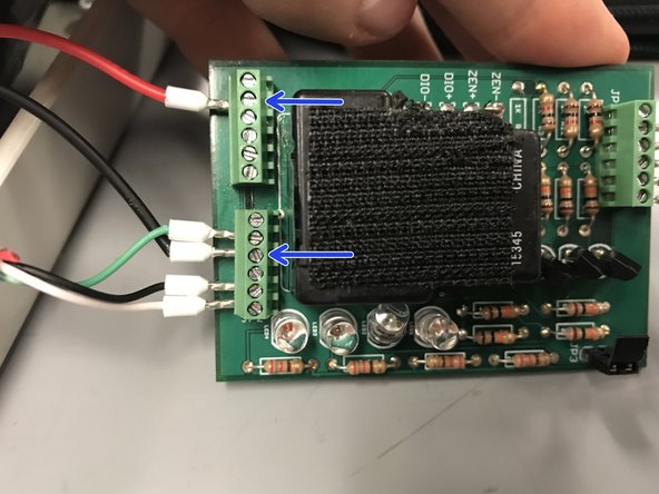
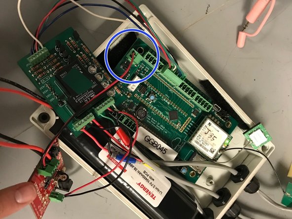
- 43. This is the back of the relay board. Make sure the blue circled pin is removed (there will be a hole). If not, the relay board must be removed. The connection must be covered up with a rubber washer. And then the relay must be soldered back on.
- 44. Place the a piece of the rough side velcro on the relay, the back of an Open-Storm board, and the battery.
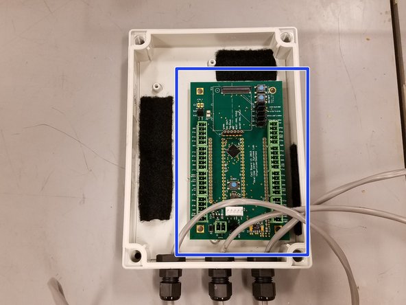
- 45. Place the Open-Storm board in the bottom right corner of the node enclosure.
- 46. Place the battery on the left side of the node enclosure.
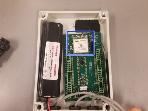
- 47. Obtain an activated and assigned cellular modem and attach a GPS antenna.
- 48. Connect the modem to the board.
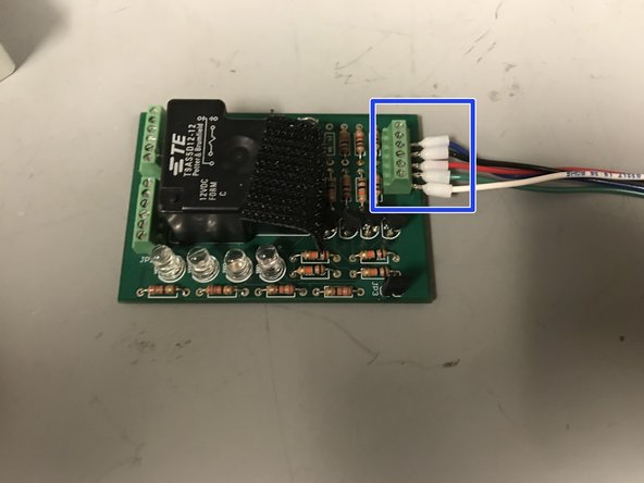
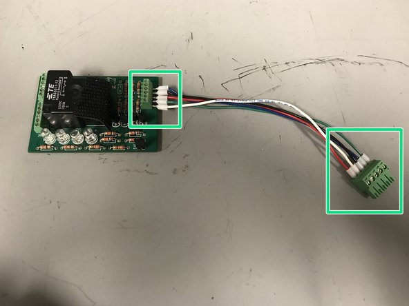
- 49. Cut five 24 AWG 6" wires: red, black, white, green, and blue. Strip about 1/4" off of both ends of all the wires. Then, use a crimping tool to attach a terminal to each end.
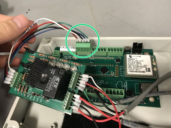
- 51. Screw in the wires into the correct spots of the five position pluggable header.
- 52. Wire the other sides into the correct spots of the screw terminal block.
- These wires go into the side of the relay board that only has one screw terminal block.
- Double check the wires are in the correct spots!
- 53. This is what the final wired relay board looks like.
- 54. Wire the green, black, and white wires from the 6-pin amphenol autosampler wire to the relay board.
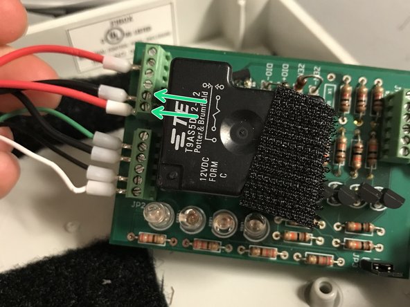
- 55. Wire the thicker red and black wires from the 6-pin amphenol autosampler wire to the relay board.
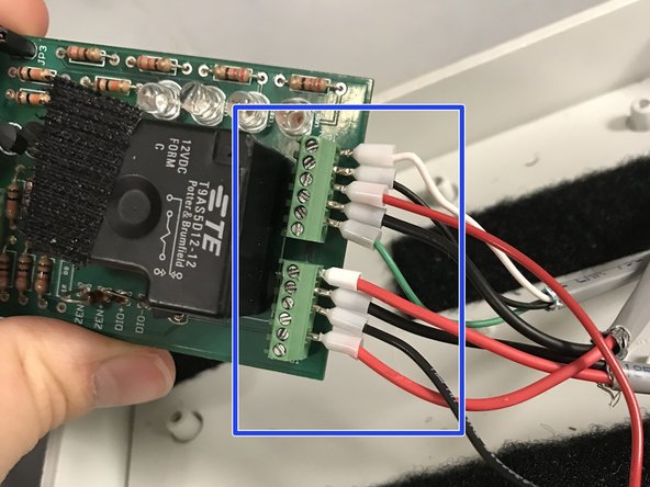
- 56. Wire the thicker red and black wires from the 2-pin amphenol battery box wire to the relay board.
- Double check it is wired correctly! The board can be shorted if wired incorrectly!
- Note: Blue, red, and yellow electrical tape was added to both ends of the grey insulated wires to made wire identification easier.
- 57. Wire the red and black wires from the Sunny Buddy solar charger to the relay board.
- 58. This is what the final relay board wiring looks like.
- 59. Plug the relay board pluggable header into the correct spot on the Open-Storm board.
- 60. Screw in the black and red wires from the battery into the Sunny Buddy solar charger.
- Make sure you match black to (-) and red to (+)!
- 61. Plug the pluggable header from the Sunny Buddy solar charger into the Open-Storm board.
- Now the node is completely wired!
- 62. Place the relay board upside down on the velco at the top of the node enclosure. Pull extra slack on the grey wires out through the glands to make more room in the box.
- 63. Screw down the lid on the enclosure completely.
- 64. This is what a completed autosampler node looks like!