Black+Decker HSV420 batteries Replacement
ID: 124855
Description: Dust buster’s have a short useful life because...
Steps:
- Remove dust collector (while you’re there, clean it)
- Remove five (5) phillips screws 003-004
- Split case 005 and lift off 006 revealing electronics board 007
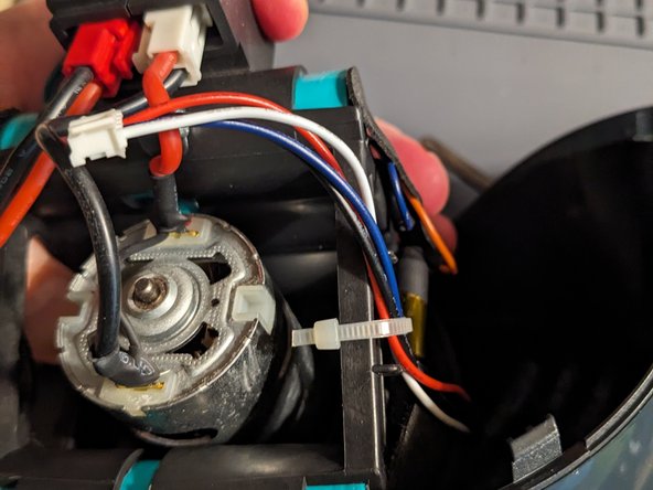
- Lift motor assembly from plastic body. Clip tie-wrap 008 and disconnect small white connector from electronics board 007 (picture 008 disappeared, but the tie wrap is the only one in there)
- Disconnect red battery connector and white motor connector 009
- Remove gasket and fan shield 010-011
- Remove two (2) screws to remove motor 012
- Note the holes into which motor mount screws go 013
- Remove three (3) screws from the battery carrier 014
- Disconnect the long white connector from the electronics board
- Split the carrier to remove the button the electronics board. 015
- Note locations of insulating tape and remove them, two from each side. 016 HEED WARNING ABOUT SHOCK!
- Pull temperature probe, that is connected to two green wires, out of assembly 017
- Cut thin ORANGE wire about a cm from heat shrink. cut thin BLUE wire about a cm from heat shrink. 018 cut thin WHITE wire about a cm from heat shrink. cut thick BLACK wire about ½ cm from heat shrink. 019 cut thick RED wire about ½ cm from heat shrink. 020
- cut thin BLACK wire from fuse next to the battery heat shrink (two places) 021-022
- Slide the right side plastic carrier off of the batteries. 023 Note that two connectors are loose. So that you can determine the orientation of the batteries (where + or - goes) in the carrier, maintain the orientation while you slide the three batteries out of the left carrier. 024
- Similarly, slide the one battery out of the left carrier. (note that there is an unused battery position.) I am going to give names to the batteries:
- a Battery that is by itself. When looking from the motor, + is on the left
- b Battery closest to the motor, + is on the right
- c Battery in the middle of the three, + is on the left
- d Battery farthest from the motor, + is on the right
- For each battery, note which side is +, the location and where the + end goes. To ensure that you know which end is +, it is recommended that you check this with a voltmeter. And you can satisfy your curiosity about the voltage of the batteries. Sometimes are so bad they reverse polarity, but that voltage would be very low.
- Take the old batteries to the place where you recycle batteries. Unpack and check voltage of new batteries (NCR 18650B, 3.6V, 3000mAhr, welded on leads, voltage less than 3V probably indicates a bad battery) 025-026
- Put the new batteries into the left half of the carrier, ensuring the + of the battery is in the same direction as its predecessor. 027
- Put the right half of the carrier over the batteries and slide into place. Do not put in the screws, yet, you still need to put in the button and the electronics. 028
- Connecting the fuse. The fuse is between + “a. Battery” and - “b. Battery” and should still be on the left carrier.
- Very carefully peel off the tape that holds the fuse to the left carrier with the hope it can be reused. The purpose of the tape is to keep the fuse from rattling. Not so much as to reduce noise, but to prevent the connection from breaking
- Strip about 1cm of heat shrink from each lead of the fuse
- Make a U-bend at the end of each fuse lead 029
- Ensure that the + lead of “a. Battery” will bend into the gap (see picture 030) This would be a good time to ensure that all of the other batteries.
- “b. Battery” lead points to “c. Battery” “c. Battery” lead points to “d. Battery” “d. Battery” lead points to “c. Battery”
- Cut red + lead of “a. Battery” leaving about 4cm. 031 Strip 1cm from lead. Tin lead
- connecting fuse, continued
- Put about 1cm of heat shrink over the lead a push it near to the battery 032
- Wrap the tinned lead 360° around the U in the fuse lead This is a one shot deal: Using the linemen’s pliers, crimp the U bend tight. The lead wire from the battery should not move. Solder the joint. Do not dwell with the soldering iron on the connection! 033
- Slide the heat shrink over the joint and shrink it with heat (I used the soldering iron)
- This is probably a good time to secure the fuse to the carrier. 034-035
- The orange wire needs to connect the the - of “b.Battery”, too. Push the thin blue and thin orange wire through the carrier. This is a good time to push the temperature sensor on the green wires into the carrier.
- Trim and tin both the orange and blue wires Put a 2cm length of heat shrink over each of the orange and blue wires. Cut the - lead of the “b. Battery” leaving about 3cm
- Strip 2cm of the lead and tin. Wrap the tinned lead 360° around the fuse lead, leaving a bit for the orange wire. Crimp the fuse lead Create a U on the “bit” of lead. Create a U on the orange wire Loop the U’s together, crimp with needle nose pliers and solder both joints, remembering not to dwell on the fuse lead 038
- Slip the heat shrink, as best you can, over both joints and shrink 039
- Solder + “c. Battery”, - “d. Battery” and thin blue wire Cut the leads of the battery wires to about 3cm , strip about ½ cm, twist together and tin.. Make a U in this joint and in the blue wire, loop U’s together, crimp with needle nose pliers, solder joint. Slip heat shrink over solder joint and shrink 040
- Solder + “b. Battery”, - “c. Battery” and thin white wire Similar to previous, but make battery leads 5cm 041
- Solder the battery connector red to + “d. Battery” and black to - “a.Battery” leads Cut battery leads to 3cm Each lead, trim, tin, 1.5cm heat shrink, loop, crimp, solder, slide heat shrink, shrink 041 Replace insulators over battery ends
- REASSEMBLY -- You're now dealing with a ~15VDC battery pack! If shorted, it will do serious damage or catch afire!
- Split battery carrier slightly and slip in electronics board 042 Align button and squeeze together battery carrier. Screw battery carrier together with three (3) screws Attach motor with two (2) screws
- Connect long thin white connector to electronics board (it is keyed, DO NOT FORCE IT!) Connect motor wires to electronics board, white connector,keyed, tab towards center CAREFUL, MOTOR MIGHT START Judiciously hold the assembly while making the connection. Connect battery wires to electronics board, red, keyed tab towards center.
- Test Hold sides of assembly, Be prepared for fan to start Press on button, fan should spin Press again to turn off. If these steps don’t happen, you did something wrong and your device is probably bricked.
- Replace fan shield, large boss (as opposed the the small boss) away from electronics board Replace gasket Connect the white connecter from the housing to the electronics board.
- Place assembly into housing. This gets a little tricky as it does not have a solid fit. Basically, the large square boss, away from the electronics board, that is part of the gasket goes into a receiving cavity in the housing. Place the cover and secure with five (5) screws.