Error-proofing of Depth Sensor Deployments
ID: 124860
Description: This guide assumes the node is already built....
Steps:
- open Anaconda Navigator
- launch Spyder
- click 'Open File' and select "node_builder.py" under "\Documents\anvil"
- click the 'Run' button
- visit this link to get started: Node Builder
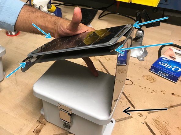
- Obtain a solar panel with the appropriate metal plate.
- Obtain the correctly bend metal plate.
- The enclosure is the box where the sensor board, and wires are kept to protect from the environment.
- Obtain the enclosure with the predrilled holes.
- Obtain the solar panel extension cable
- Obtain heat-shrink tubing and place it around the cable
- Cover the connection between the solar panel wire and the extension cable with the heat-shrink tubing. Then, use a heat gun to shrink the tubing, creating a water-tight seal around the connection
- Trim the solar panel extension wire so there is approximately 20 inches of wire from the connection point
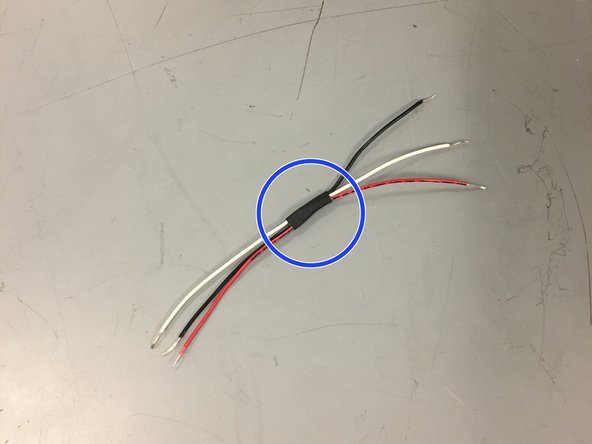
- Strip the wires as shown in the image
- Twist the ends of the wires
- Attach the solar panel onto the metal plate.
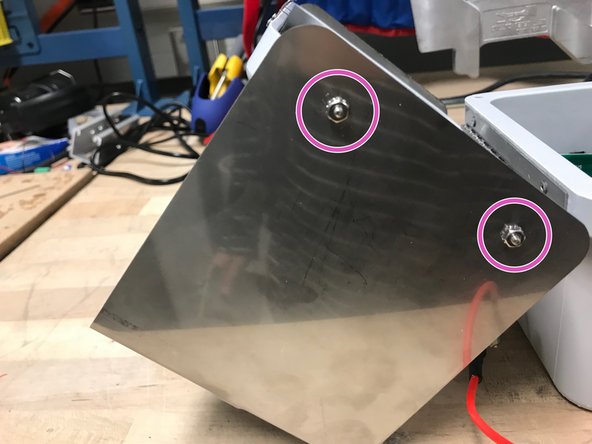
- Using screws and a screw driver, screw the solar panel into these holes. Now that the solar panel is attached to the metal plate, attach the metal plate onto the lid of the enclosure
- Note: the tall side of the metal plate should be on the same side of the enclosure as the holes for the ultrasonic sensor and cable glands.
- The screws and nuts should be screwed in this matter in the holes on the sides of the box lid (meaning the nut is on the outside)
- Obtain velcro
- Add velcro with soft side inside the enclosure in the following places
- Now we need to insert the red extension wire from the solar panel into the enclosure box
- Obtain a cable gland
- Screw the cable gland into the wall of the enclosure, through the small hole, as shown
- Place an o-ring between the cable gland and outer-wall of the enclosure
- Insert the solar panel extension wire into the cable gland as shown, leaving approximately 8 inches of wire inside the enclosure
- Obtain a plugable header and ensure the ends of the wires are twisted
- Screw the wires into the plugable header as shown in the picture
- Note: hand tight is just right.
- Solder a 3-prong terminal block to the ground, power, and data (#5) through-holes on the depth sensor
- For organization, bind three wires (red, white, and black) with a small piece of shrink wrap
- Connect the wires as shown in the picture (black to ground, red to power, white for data)
- Assemble the depth sensor by adding the o-rings, and the connective wires in the order pictured, leaving the nut ring to the side
- Note that the connective wires connect the depth sensor to the sensor node board. Remember, red wire is responsible for power, black is for ground, and white is for data
- Place the depth sensor through the larger hole, and secure it firmly by tightening the nut ring
- Make sure the nut ring is tightened securely as it will keep the enclosure water-tight
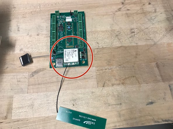
- Obtain the cell module (modem), GPS, and antenna
- Insert Super SIM card into cell module
- Attach the GPS to the connection shown (grey wire)
- Attach the antenna to the connection shown (black wire)
- Attach rough-sided velcro on the antenna and GPS as shown in the picture.
- Obtain velcro and lithium ion 3.7V battery. Attach rough side of velcro on battery
- Be very careful not to short the battery by touching the two wires together.
- Obtain a block plug.
- Twist the wires of the battery so they fit nicely in the plugable-header block
- Screw the wires into the block plug
- Note: hand tight is just right.
- Obtain one battery, 4 zip ties, foam, and a pair of scissors
- Cut out two battery-sized pieces of foam
- Sandwich the battery between the two pieces of foam and secure it using the zip-ties. Connect the zip-ties to make two extra long zip-ties
- Obtain eight 1.5-inch long standoffs. Screw the standoffs together as shown, to make four 3-inch long standoffs
- Screw the standoffs into the enclosure
- Insert battery into the enclosure. Make sure the wire is on the sensor-side of the enclosure
- Obtain Open-Storm board and place 4 jumpers in the spots shown
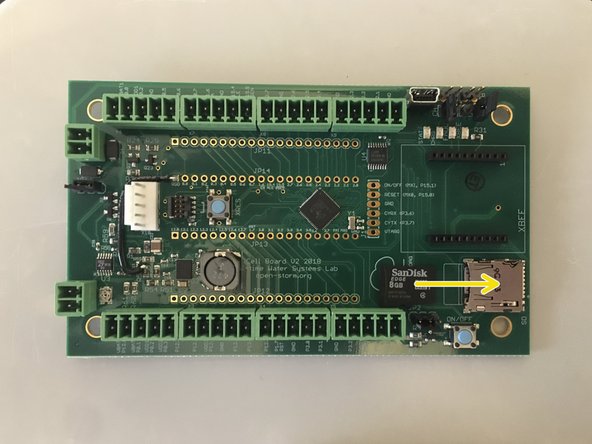
- Insert microSD card into board
- Attach the cellular module onto the sensor node board in the appropriate place
- Put the board on top of the standoffs in the enclosure, and screw it in using a screw driver
- Connect the depth sensor wire as shown
- Connect the solar panel wire to the board as shown
- Connect the battery wire to the board as shown
- Attach the antenna, and the GPS on the velcro to the closest wall on the inside of the enclosure
- apply the open-storm sticker to the side of the enclosure as shown
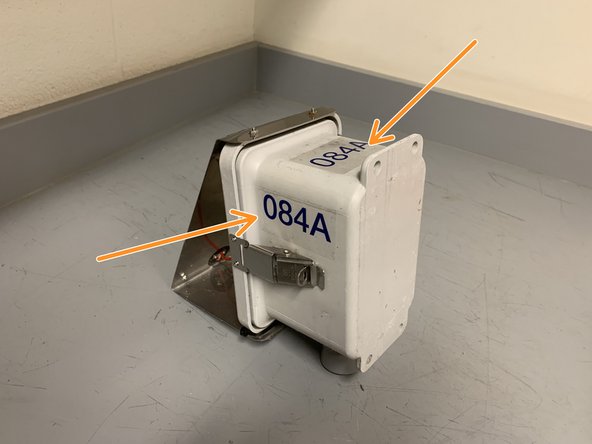
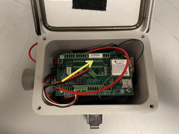
- apply the unique node ID sticker to the two spots shown
- print a label with the unique node ID that appears on the sticker using the label maker
- apply the label to the board as shown
- Fold wire over itself so that the portion above the hose clamp won't have slack when the black wire section is pressed against the inside of the panel
- Obtain a hose clamp, and secure the red part of the wire to the black section using a drill fitted with the drill bit
- Wrap a zip tie around the wire as shown.
- Use a second zip tie to connect the ends of the first one
- Use a clamp to tighten the zip tie
- Position each zip tie head as shown while tightening
- Clip excess zip tie as close as possible
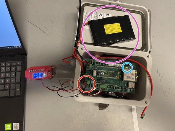
- Obtain USB power supply, plug into a laptop, and set output to 5.9V
- Check the voltage with a voltmeter (you may have to set the power supply to ~5.8V for the voltmeter to read 5.9V)
- Plug in the green terminal block from the power supply into the Open-Storm board solar port.
- Confirm the solar charge LED is off.
- Plug in a dead battery to the battery port. This step will not work with a charged battery
- CAREFULLY turn the silver potentiometer next to the charge controller IC with a small flathead screw driver until the charge light turns on.
- Although the screw has a phillip screw head, using a phillip screwdriver may damage the potentiometer. The hole in the center is too shallow for most screwdrivers. It is easier to use a flathead screwdriver!
- Resource: 1. How to Select MPP Voltage on a Solar Charge Controller 2. Sunny Buddy Solar Charger V13 Hookup Guide
- obtain a master lock and a pair of scissors
- cut the lock and key out of the packaging
- set the lock to the default combination, 0-0-0-0, open the lock
- put the key into the lock and twist clockwise 90 degrees
- while the key is still twisted, set the combo to 2-2-4-5
- remove the key, and the lock is ready to go
- obtain the materials in the quantities shown
- screw the U-bracket onto one of the 8" strut channels, using one of the 1/2" hex bolts and the 1/2" strut channel nut
- attach the remaining 8" strut channel piece to the U-bracket, using two 1/2" hex bolts and two 1/2" hex nuts
- be sure not to center the strut channel you are attaching the the U-bracket, instead make one side of the U-bracket flush with end of the strut channel (as shown)
- insert the two 5/16" strut channel nuts into the back of the horizontal strut channel as shown
- attach the winged strut channel bracket to the 8" telespar using the remaining two hex bolts and hex nuts
- when tightening the hex nuts, ensure the edge of the nut points directly outwards (as shown), or else the struct channel piece will not slide inside
- confirm the T-shaped strut channel piece slides into the telespar, and the handle is now finished
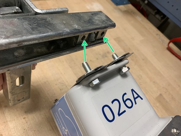
- Attach the reinforcement rails to the back of the node using two 5/16" hex bolts, two 5/16" hex bolts, and two 5/16" 1.25" OD washers. Insert the bolts the bottom two holes of the node enclosure, using the bottom holes of the rails as shown in the image.
- Line up the top holes of the rails with the top node enclosure holes and then tighten the bottom bolts.
- screw the node enclosure onto the strut channel using the two 5/16" hex bolts and two 5/16" 1.5"OD washers. Be sure to put bolts through the reinforcement rails.
- removing the T-shaped strut channel piece from the telespar makes this step easier
- slide the T-shaped piece back into the telespar
- this is what the node should look like on the inside
- make sure the battery is plugged in
- attach the lock to the outside of the enclosure
- return to Node Builder for instructions on how to drop off the node at the testing rack
- In-lab: Make sure the sensors node is connected to the cell network. Ask administators to connect it if it's not.
- If doing this by yourself then follow the next steps:
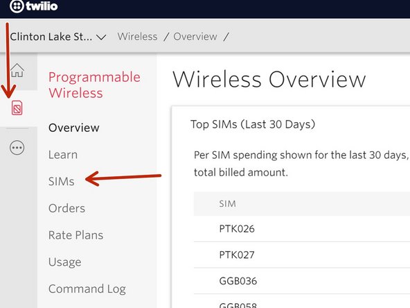
- Step1: Check for "Active" on the Twilio website. Use the MEID to search the SIM repositoy on Twilio. If it's active then you are done.
- Step 2: If the search on Twilio did not return anything then check the Node has a SIM card. If yes, then check and update the 'SIM-Node ID pairings' spreadsheet here. If the Node does not have one, get a SIM from an admin and fill in the spreadsheet linked above.
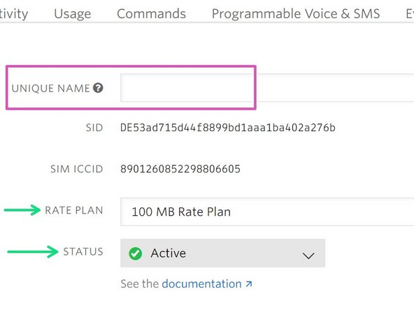
- Step 3: After the node gets a SIM card and the infomation is logged in the 'SIM-Node ID pairings' spreadsheet proceed to activate the SIM card. You will have to log into the Twilio website and activate it. Consult the attached picture to see how the setting should be set.
- Unique Name = Node ID (i.e PTK001). If the Node ID is already taken then doulbe check the ID parings here. If it's all good, then edit all the Twilio unique names accordingly.
- Insert a fully charged battery into the sensor node. Plug in the battery before the solar charger.
- Make sure the battery leads are wired correctly. The terminal block and leads are shown here.
- A green LED light on the cell modulem should turn on.
- Make sure that there is an O-ring on outside of the node.
- make sure to tighten the screw on the inside snuggly.
- Make sure the wires are connected in this manner. From the edge it should be "black, red, white". The ultrasonic sensor has labels on it and GND (ground) is on the very end. Hence, the black wire on the end.
- The other ends of the wires are connected to a 5-prong terminal block. That terminal block should be connected to the board at the following pins: P12.3 : White wire, P12.4 : Red wire, GND : Black wire.
- Make sure all the jumpers on the board are connected properly. They are labeled JP1 and JP2
- can use the mnemonic "top-down, bottom-up".
- Another view.
- These jumpers should be disconnected when ready to deploy. This is done to save battery.
- The Node ID is determine by the location where the node will be deployed. Ask and administator where to deploy. Then, find all the site details here.These include site visits, pictures, addresses, and notes.
- Ask admin to do this step. Alternatively, ask admin for the scripts that assigns the Node ID and the reporting time interval. Assign both using the Anaconda Navigator's Jupyter Notebook feature. You will need the sim card's MEID and the desired Node ID to do this. The google drive has a spreadsheet with MEID's and Node ID's here. Keep this updated.
- Set the reporting frequency to 5 minutes!
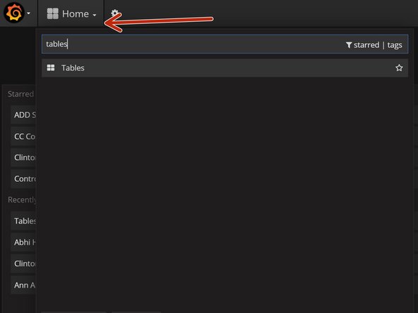
- Once assigned, the readings will be pushed to Grafana. To double check that it was assigned successfully you can consult the 'Tables' Dashboard on Grafana. Ask administarator for Grafana credentials.
- Assumption: you have the Grafana credentials.
- Use an existing Dashboard (i.e. Abhis Hostage Nodes) or create one.
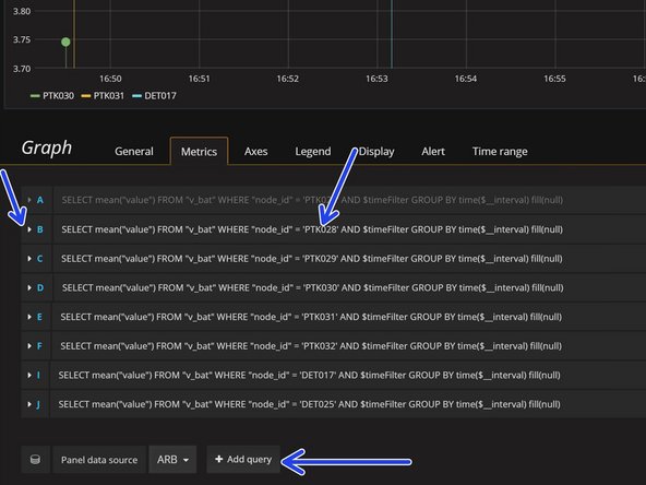
- To enter the edit panel click the header and it will appear. If you created a new dashboard, then you must create a 'v_bat' panel and a 'maxbotix_depth' panel. They should be labeled to indicate battery voltage and depth. Always save changes frequently.
- Once inside the edit panel: It's possible to edit an already existing entry and only update the Node ID and alias. Alternatively can click on 'add query'. When adding a new query get an admin to supervise while you do it.
- Use this dashboard exclusively for testing and delete already deployed nodes. Sensors that have been deployed should be promoted to their permanent Grafana Dashboard. i.e: Cinton River, Huron River,...
- Click on the nodes INDIVIDUALLY to see that the reported values are sensible. If the depth reading is -1 then there is an ultrasonic sensor problem. If the depth value is 0, then the ultrasonic sensor does not have 0.5 meters of required space between itself and what it's reading.
- Node must report successfully for 12 hours
- Bring at least 1 extra working nodes when deploying!
- Find the address by viewing the site visit documetation here. Read the notes about the potential hazards and where to park.
- prepare emergency phone numbers and note the closest urgent care.
- Choose nodes that are close near each other. Use Google Maps 'add-a-stop' feature to check proximity.
- Make sure to take all required tools. The tools required should be deduced from the site visit inspection and notes corresponding to the location.
- The van already has a tool kit. The google drive has a document specifying which tools belong in the van.
- Collect hardwarespecific to sites, enough fully charged batteries for nodes, at least one fully charged 12v battery, enough locks, and drinking water.
- Hardware inlcude strut channel, bolts, nuts, brackets, C-clamps, etc.
- Pump gas here.
- Upon ARRIVING to every site, fill this google form.
- Upon LEAVING every site, fill this google form.
- After the node is deployed and there is no interference from it being hadled, wait for a reading.
- The reporting frequency should have been set to 5 minutes! As required in step 21 of this guide.
- If the reading doesn't appear or it's -1, then reach out to someone in lab to reassign a working node to that location. Take the faulty node back to lab. Donnot diagnose in the field.
- Assumption: You brought extra working nodes.
- Requirement: Bring extra nodes.