La Pavoni Espresso Plus Dissassembly
ID: 124984
Description: The disassembly of the La Pavoni Espresso plus...
Steps:
- Unplug the machine from any power source(s).
- Remove the water tank.
- The cover is held in place with two Phillips screws (PH1). Loosen the screws and remove the cover.
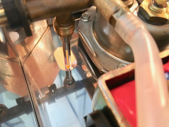
- Loosen the grub screw on the stopper (black plastic part) with a 2mm Allen key.
- Pull stopper over to the side of the machine.
- Unscrew the steam valve. The plastic toggle can remain attached.
- If necessary, clean the steam valve with descaler.
- If there is a leak, the two O-rings must be replaced.
- Push the black plastic cover down and out of the bottom of the case. Then, unscrew the union nut (wrench size 13).
- Pull the steam pipe down and out of the housing.
- Once you have dismantled the steam pipe, you may choose to decalcify it and replace the O-rings if there are any leaks.
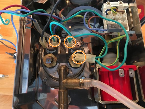
- Disconnect the left connection of the heating coil (blue) and the right connection of the right thermal switch (single green wire).
- Now disconnect the second green cable. It connects the heating coil to the right thermal switch on the left connector and the left thermal switch on the right connector.
- Disconnect the black wire at the left thermal switch and the green/yellow wire at the ground point. Pull out the temperature fuse (in the transparent plastic tube) under the ground point. To do this, lift the tab slightly.
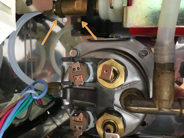
- Unscrew the four cap nuts (8mm nuts) on the portafilter holder.
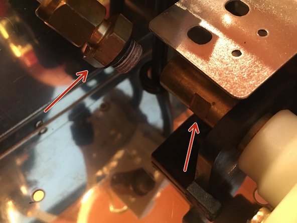
- Unscrew the pressurized water line at the pump. Two wrench sizes (SW12 and SW14) are required for this. SW12 is used to hold the pump, and SW14 is used for the union nut. Then, detach the pressure hose.
- Take a detailed photo of the connection(s) for reference
- You can now remove the brew-group completely out of the machine.
- Loosen the four screws. Be careful, as water will run out. Width across flats is 8.
- Pull the two halves of the kettle apart. If they are calcified and sticky, tapping them lightly will help.
- You now have an interior view of the boiler. The limescale usually collects at the bottom of the boiler. Replace the O-ring if it is brittle or leaking. The heating coil and its two seals can also be replaced at this point.
- Overview of the brewing group: Boiler and portafilter holder.
- The shower screen is attached with a small slotted screw.
- The portafilter seal can now be pulled out.
- At this point, take the opportunity to clean all components thoroughly.
- Unplug cable.
- Pull off the hose to the water tank, by first loosening the clip with pliers.
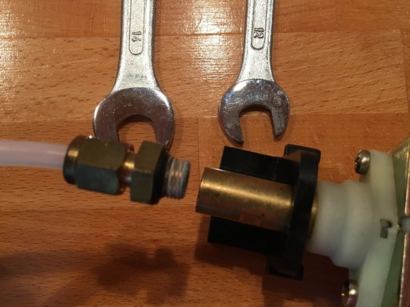
- Disconnect the pressure hose. Use size 14 on the union nut and size 12 to hold the pump in place (the electric terminal was clipped off the holder for the photo).
- Open the fastening nipple from below, use a 2mm punch or wire and press the mandrel out of the nipple. The pump can now be lifted out of the machine.
- Take a detailed photo(s) of the removed pump and the mounting nipples.
- The rubber mounts of the pump can now be easily removed; the rubber connector on the left must also be removed to do this.
- The valve is located at the connection for the pressure hose on the left-hand side.
- Top view (excluding the rest of the pump): Use pointed tweezers to open and unscrew the black plastic (right-hand thread).
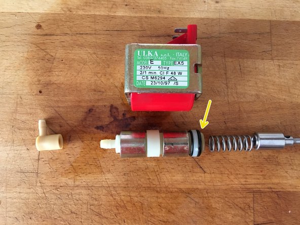
- The disassembled valve: If necessary, replace the spring and the rubber mushroom if the pump is leaking at this point. Sometimes the valve is also stuck, then cleaning helps.
- To re-assemble, simply push on the plastic grid as far as it will go.
- Before disassembling the pump, pull off the rubber holders and the rubber nozzle.
- Unscrew the two screws (PH1). The pump can now be pulled out of the coil housing (red plastic housing).
- The pump is held together by a bayonet lock.
- Check all springs for breaks and rubber for cracks. If the small plastic ball has become too small and falls into the tube, it must be replaced.
- The O-ring likes to harden and then no longer seals. 5x2 is the dimension.