MFC-J4410DW Flushing Box Replacement
ID: 125058
Description: When "Ink Absorber Full" or "Ink Absorber Near...
Steps:
- Before beginning disassembly, turn off the printer and unplug the power cord.
- Open the front access door and remove any cards or cables present. Close the access door.
- Remove the paper tray.
- Remove the ink cartridges.
- You may wish to install the Protective Part to prevent the ink tubes from drying while the cartridges are removed.
- Open the printer cover using the finger holds on the sides.
- Unplug and remove any cords present under the cover.
- Remove the LAN port and EXT port caps (if present).
- While holding the cover with one hand, pull the hook on the back of the support damper, then remove the damper from the cover.
- Remove the damper from the support.
- Turn the support upright and pull it straight out of the printer.
- Use your finger or a spudger to unhook the two tabs on the right side of the harness cover by levering it up.
- Remove the harness cover. There are two tabs on the left side that you have to wiggle free, and one on the front.
- Remove the 6 mm Phillips #2 screw from the grounding wire of the ADF motor harness.
- Torque: 0.40±0.10 N•m
- The Brother service manual lists torques for all screws, but proper torque should not be necessary.
- In the proceeding steps, you will disconnect the following cables:
- CIS flat cable
- Scanner motor harness
- ADF motor harness
- Document detection/document scanning position sensor harness
- Pull the CIS flat cable out of its socket.
- Pull all flat cables directly up out of their sockets, pulling on the cables themselves at the blue tabs.
- Pull the scanner motor harness out of its socket.
- Pull the ADF motor harness out of its socket.
- Pull the document detection/document scanning position sensor harness out of its sockets.
- Insert a spudger between the scanner harness holder and frame to release the tab. There is a second tab on the opposite side.
- Lift the scanner harness holder out of its frame.
- Reassembly Note: Before reattaching the harness holder, it is advisable to reattach the cover support (Step 2) to minimize tension on the wiring harnesses.
- Push on the tab to secure the scanner harness holder to the scanner cover.
- De-route the document detection/document scanning position sensor harness and the ADF motor harness from the scanner harness holder.
- During reassembly, put a 20mm-thick pad (book, stack of paper) on the scanner glass, close the scanner cover, then route the document detection/document scanning position sensor harness and the ADF motor harness through the harness holder. This will ensure the proper harness tension to allow scanning of thick books.
- Using both hands, pull the scanner cover to the rear while holding it vertically, then lift it off of the printer.
- Remove the six 12 mm Phillips #2 screws securing the upper cover to the printer.
- Torque: 0.70±0.10 N•m
- Pull off the upper cover.
- When reinstalling, ensure that the control panel wiring holder slides into its slot on the upper cover.
- Remove the ink absorber full sensor from its socket.
- De-route the wiring from its harness.
- Unclip the ink absorber from the harness by pulling it up and to the right.
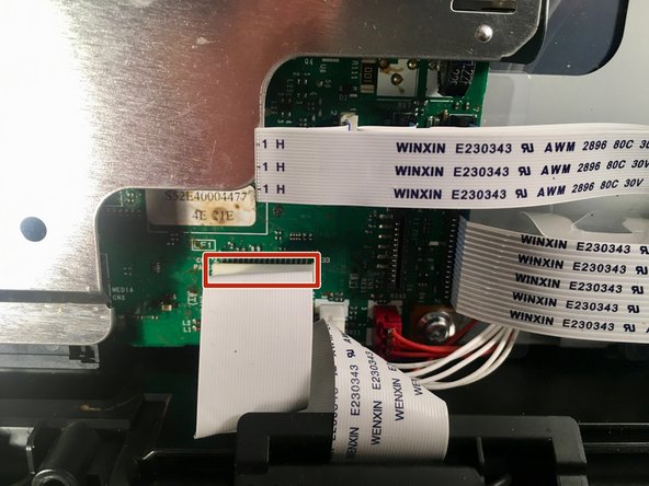
- Remove the MJ PCB flat cable.
- De-route the MJ PCB flat cable.
- Remove the 6 mm Phillips #2 screw securing the MJ shield.
- Torque: 0.40±0.10 N•m
- Remove the MJ shield.
- Remove the 6 mm Phillips #2 screw securing the MJ PCB assembly.
- Torque: 0.40±0.10 N•m
- Pull back on the MJ PCB assembly release tab.
- Remove the MJ PCB assembly.
- Release the upper hook on the front cover.
- Pry the front cover off. Note the tab on the left side of the cover.
- Open the media module cover.
- Release the two hooks holding the inner media module cover to the printer.
- Remove the inner media module cover.
- You can close the media module cover after this to get it out of the way.
- Remove the power supply PCB harness from the main PCB assembly and de-route it from the main PCB frame.
- Remove the following wiring harnesses from the sensor relay PCB assembly, and de-route them from the main PCB frame:
- Paper feed encoder sensor harness
- Switchback sensor harness
- It may be easier to wait to de-route the carriage motor harness and paper feed motor harness before de-routing the switchback sensor harness.
- Remove the following wiring harnesses from the main PCB assembly and de-route them from the main PCB frame:
- In the process of de-routing these harnesses, pull straight up on the attached magnets to dislodge them from their retainers.
- Paper feed motor harness
- Carriage motor harness
- Remove the control panel flat cable.
- Remove the ink refill sensor flat cable.
- Remove the following cables:
- Carriage PCB flat cable 1
- Carriage PCB flat cable 2
- Carriage PCB flat cable 3
- Remove the following wiring harnesses attached to the main PCB frame:
- Speaker harness
- Ink cover sensor harness
- Purge cam sensor harness
- Registration sensor harness
- Remove the 6 mm Phillips #2 screw securing the control panel grounding wire.
- Torque: 0.40±0.10 N•m
- Remove two 10 mm Phillips #2 screws securing the main PCB frame.
- Torque: 0.40±0.10 N•m
- Remove the final 6 mm Phillips #2 screw securing the main PCB frame.
- Torque: 0.45±0.10 N•m
- Remove the 6 mm Phillips #2 screw securing the FG wire.
- Torque: 0.40±0.10 N•m
- Unhook the tab of the clear plastic wiring holder.
- During reassembly, ensure that the plastic tab on the right goes into the slot behind the flat cables.
- Remove the main PCB frame.
- Before reinstalling, ensure that the ink tubes beneath are not crimped.
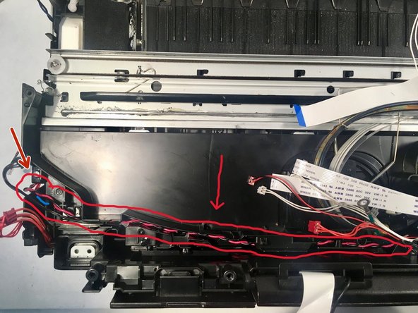
- De-route the switchback sensor harness (black) and the paper feed motor harness (red and black) from the left side of the tube support plate.
- De-route the speaker harness (red and black), purge cam sensor harness (white, three-wire), registration sensor harness (orange), ink cover sensor harness (white, two-wire), carriage motor harness (red and black), and FG wire (green) from the right side of the tube support plate.
- De-route the ink refill sensor flat cable from the tube support plate.
- Remove the left 10 mm Phillips #2 screw holding down the tube support plate.
- Remove the center 10 mm Phillips #2 screw holding down the tube support plate.
- Remove the right 10 mm Phillips #2 screw holding down the tube support plate.
- Torque for all three screws: 0.40±0.10 N•m
- Tilt open the control panel to release the tilt hook stopper.
- There's a button on the underside of the control panel to allow it to fold back in.
- Release the retaining tab with your finger or a metal spudger.
- Remove the tube support plate.
- There's no need to remove the ink tubes and flat harnesses. Just set the tube support plate out of the way on the printer. Take care not to crimp the ink tubes.
- When reinstalling, make sure the black switchback sensor harness does not get left under the tube support plate.
- Open the jam clear cover.
- Push the lower right side cover in the direction of the arrow to release its hooks from the printer. A metal spudger may be of use here.
- Pull the lower right side cover to the rear to release its hooks and remove it from the printer. Again, using a metal spudger to pry it to the rear may be useful.
- De-route the FG wire (green), the purge cam sensor harness (white), and the registration sensor harness (orange) from the right side of the machine.
- Remove the magnet attached to the carriage motor harness (red and black) from its slot.
- Remove the left carriage frame spring by pulling back on the tab on the bottom.
- Turn the paper feed roller gear in the direction of the arrow until the head stopper of the maintenance unit clicks.
- From this step on, it might be a good idea to wear nitrile gloves to protect your hands from ink stains. But don't worry; they wash off easily.
- Slide the head/carriage unit to the removal slot position at the far left. Don't remove it yet.
- This is the removal slot.
- Remove the right carriage frame spring.
- Remove the two 10 mm Phillips #2 screws holding down the carriage frame assembly.
- Torque: 0.60±0.10 N•m
- Lift the carriage frame assembly out of the printer, making sure to keep the head/carriage unit over its release slots.
- When reinstalling, make sure it's seated properly. It may require some wiggling, but it will fit firmly when placed correctly.
- Note these hooks, which have to be disengaged from the switchback frame assembly in front of it during removal. Just wiggle the carriage frame assembly around while lifting, and they should come loose.
- Remove the flushing base by lifting it straight upwards.
- You'll want a folded tissue or paper towel to set this down on.
- The flushing base, removed.
- Remove the flushing box by disengaging the front hook, then tilting it up to disengage the rear hook.
- When reinstalling, just press it straight down.
- The flushing box, removed.