MFC-J4410DW Ink Absorber Box Replacement
ID: 125060
Description: When "Ink Absorber Full" or "Ink Absorber Near...
Steps:
- Before beginning disassembly, turn off the printer and unplug the power cord.
- Open the front access door and remove any cards or cables present. Close the access door.
- Remove the paper tray.
- Remove the ink cartridges.
- You may wish to install the Protective Part to prevent the ink tubes from drying while the cartridges are removed.
- Open the printer cover using the finger holds on the sides.
- Unplug and remove any cords present under the cover.
- Remove the LAN port and EXT port caps (if present).
- While holding the cover with one hand, pull the hook on the back of the support damper, then remove the damper from the cover.
- Remove the damper from the support.
- Turn the support upright and pull it straight out of the printer.
- Use your finger or a spudger to unhook the two tabs on the right side of the harness cover by levering it up.
- Remove the harness cover. There are two tabs on the left side that you have to wiggle free, and one on the front.
- Remove the 6 mm Phillips #2 screw from the grounding wire of the ADF motor harness.
- Torque: 0.40±0.10 N•m
- The Brother service manual lists torques for all screws, but proper torque should not be necessary.
- In the proceeding steps, you will disconnect the following cables:
- CIS flat cable
- Scanner motor harness
- ADF motor harness
- Document detection/document scanning position sensor harness
- Pull the CIS flat cable out of its socket.
- Pull all flat cables directly up out of their sockets, pulling on the cables themselves at the blue tabs.
- Pull the scanner motor harness out of its socket.
- Pull the ADF motor harness out of its socket.
- Pull the document detection/document scanning position sensor harness out of its sockets.
- Insert a spudger between the scanner harness holder and frame to release the tab. There is a second tab on the opposite side.
- Lift the scanner harness holder out of its frame.
- Reassembly Note: Before reattaching the harness holder, it is advisable to reattach the cover support (Step 2) to minimize tension on the wiring harnesses.
- Push on the tab to secure the scanner harness holder to the scanner cover.
- De-route the document detection/document scanning position sensor harness and the ADF motor harness from the scanner harness holder.
- During reassembly, put a 20mm-thick pad (book, stack of paper) on the scanner glass, close the scanner cover, then route the document detection/document scanning position sensor harness and the ADF motor harness through the harness holder. This will ensure the proper harness tension to allow scanning of thick books.
- Using both hands, pull the scanner cover to the rear while holding it vertically, then lift it off of the printer.
- Remove the six 12 mm Phillips #2 screws securing the upper cover to the printer.
- Torque: 0.70±0.10 N•m
- Pull off the upper cover.
- When reinstalling, ensure that the control panel wiring holder slides into its slot on the upper cover.
- Remove the ink absorber full sensor from its socket.
- De-route the wiring from its harness.
- Unclip the ink absorber from the harness by pulling it up and to the right.
- For this step, spin the printer around so the back is toward you.
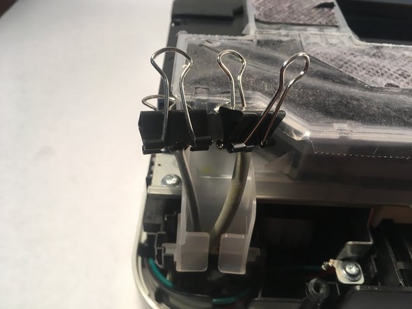
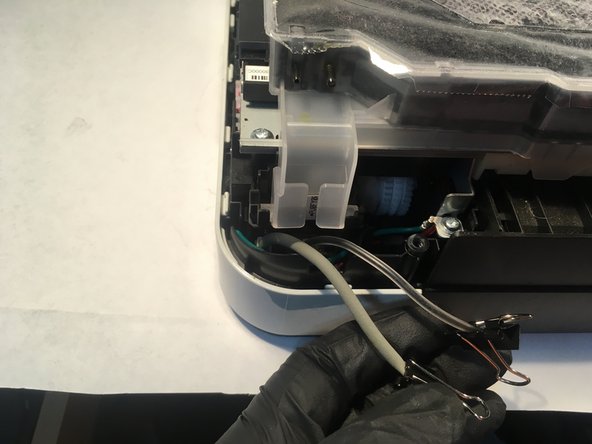
- Remove the drain tube and the air vent tube from the ink absorber box. A spudger may be helpful.
- Clip the ends of the tubes so they won't leak.
- De-route the tubes from the holder.
- Rotate the ink absorber box 90º vertically, and pull it up out of its socket.