Acer Iconia Tab A501 Touch Screen/Glass Replacement
ID: 125123
Description: One of the most common repairs on modern...
Steps:
- Turn off your device before opening it.
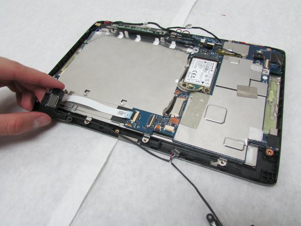
- Use a plastic opening tool to carefully separate the back cover, starting at the volume buttons.
- Continue separating the back cover along the short side closest to the camera and around the device.
- When separated enough, a little more than halfway around the device, the back cover will be easy to take off.
- Remove all tape from the device.
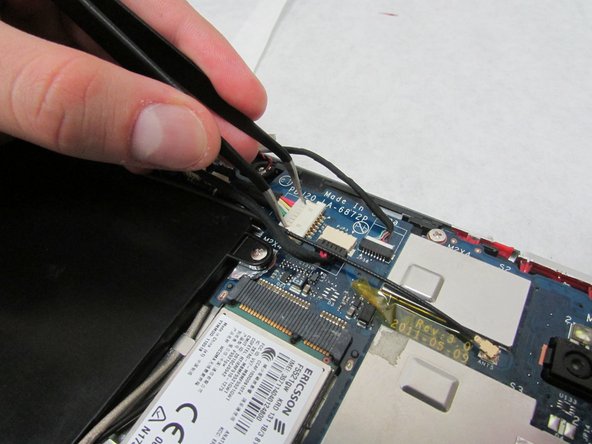
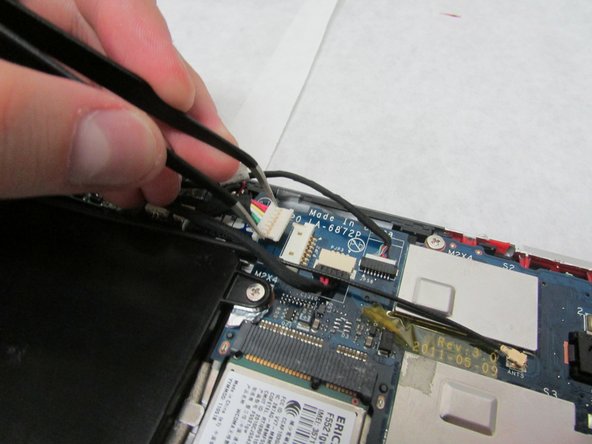
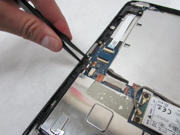
- In the next step, be careful not to squeeze too hard or scratch the motherboard.
- Use the angled tweezers to disconnect the motherboard-battery cable from the white connector in the middle of the side opposite the docking port.
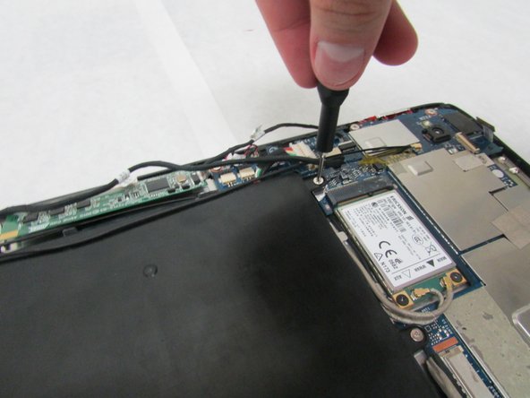
- Use a Phillips #1 screwdriver to remove the four 4.0 mm Philips head screws connecting the battery to the motherboard.
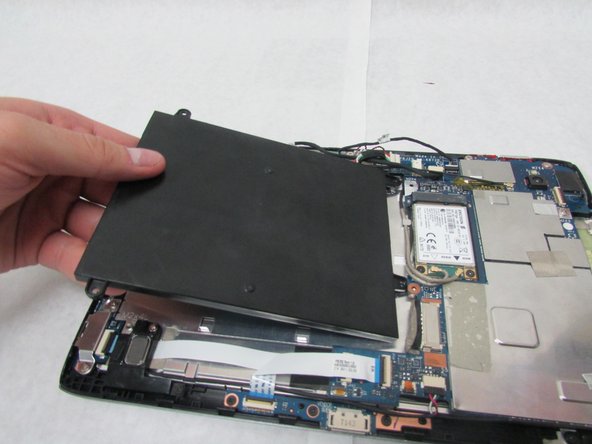
- Take out the battery.
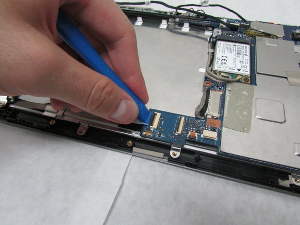
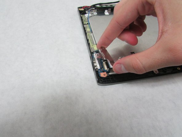
- Use the plastic opening tool to flip up the locking mechanism on the motherboard connected to the folded, white ribbon cable.
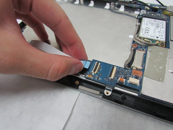
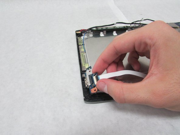
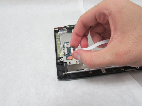
- Remove the folded, white cable.
- Use a Phillips #1 screwdriver to unscrew the three 3.0 mm Philips head screws holding the docking port in place.
- Remove the docking port.
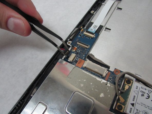
- In this step, be careful not to squeeze too hard or scratch the motherboard.
- Use the angled tweezers to disconnect the cable with red, white and green wires from the beige connector slightly in from the docking port.
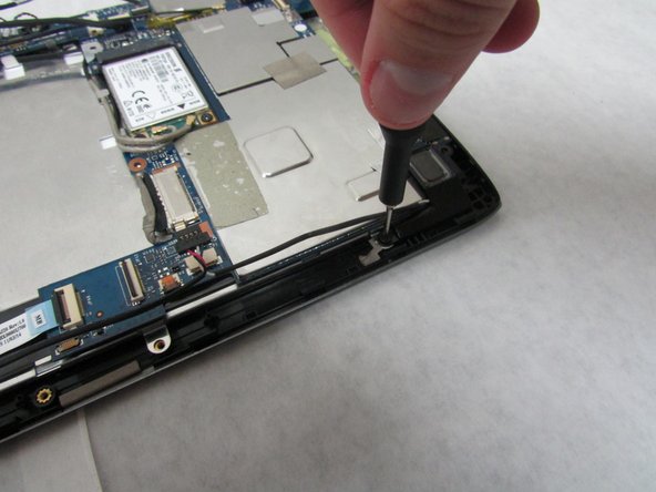
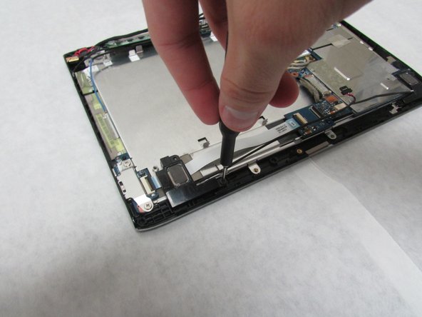
- Unscrew the 3.0 mm Phillips head screw on each speaker using a Phillips #1 screwdriver.
- Unscrew the 4.0 mm Phillips head screw on each speaker using a Phillips #1 screwdriver.
- Remove the speakers.
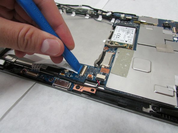
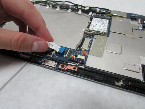
- Use the plastic opening tool to flip up the locking mechanism on the motherboard connected to the straight, white ribbon cable.
- Remove the straight, white ribbon cable.
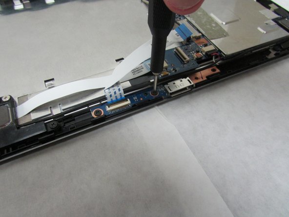
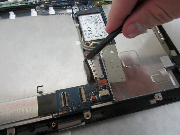
- Use a Phillips #1 screwdriver to remove the two 4.0 mm Philips screws attaching the metal plate, USB board, and device.
- Remove the metal plate.
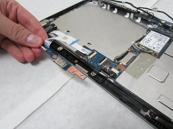
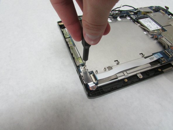
- Use the Halberd Spudger to carefully pop up and take out the ports.
- Use care in the next step.
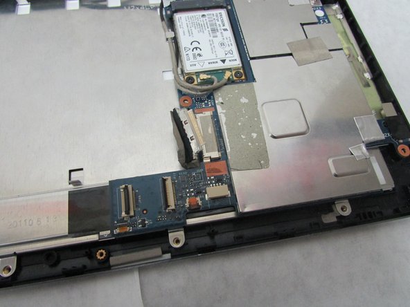
- Use the wide, flat end of the standard Spudger to disconnect the display connector from the large, metal port next to the battery space.
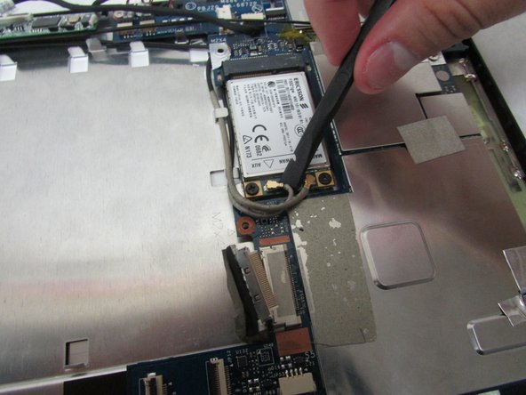
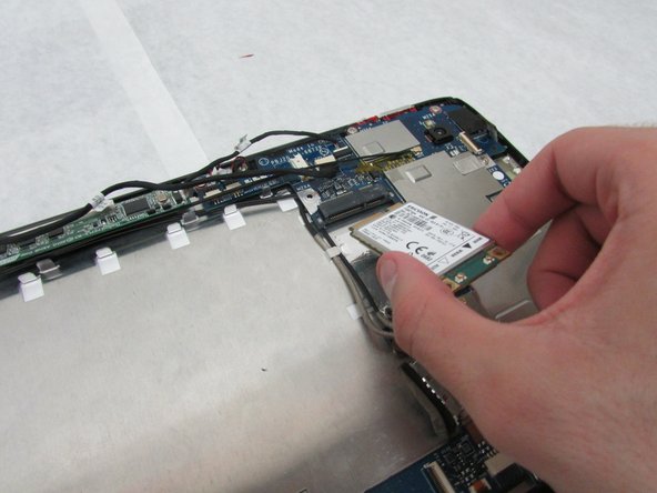
- Use the flat end of the standard Spudger to disconnect the two small, rotatable connectors attached to the wireless adapter.
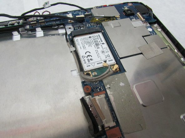
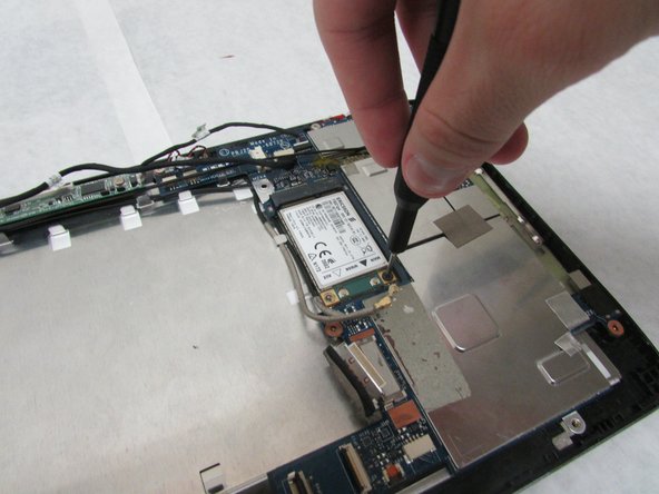
- Use a Phillips #1 screwdriver to remove the two 3.0 mm Philips head screws holding the adapter down.
- Carefully slide the adapter out to remove it.
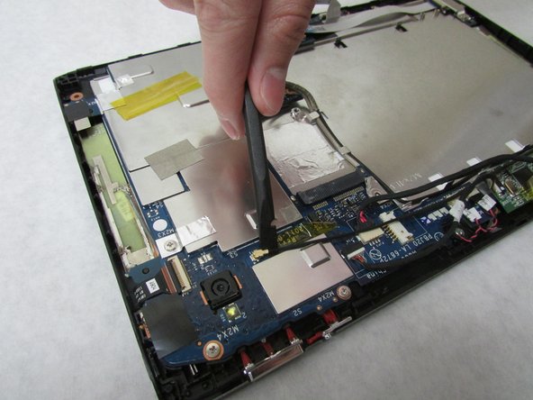
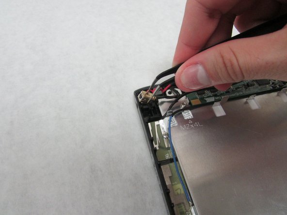
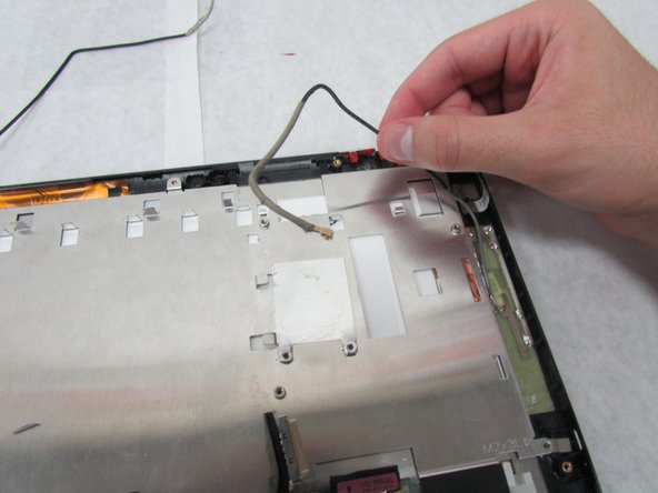
- Use the wide end of the standard Spudger to take off the rotatable connector to the 3g antenna below the rear-facing camera.
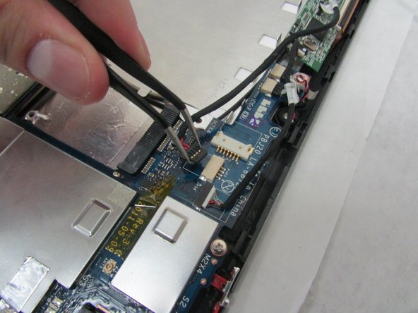
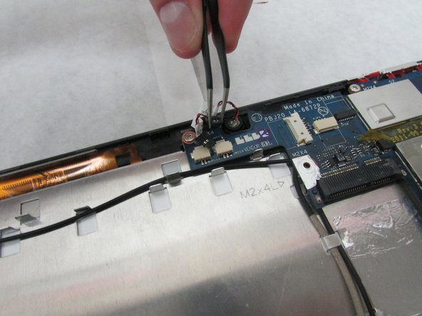
- In the next step, be careful not to squeeze too hard or scratch the motherboard.
- Use the angled tweezers to disconnect the cable with red wires from the beige connector opposite the docking port.
- The charging port may be taped from underneath and need a bit of force to take out.
- Use the angled tweezers to remove the charging port.
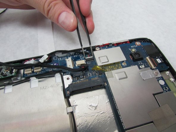
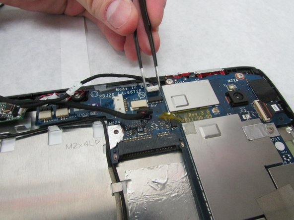
- In this step, be careful not to squeeze too hard or scratch the motherboard.
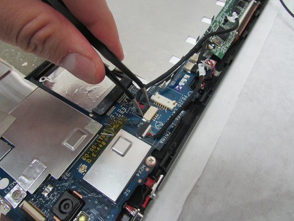
- Use the tweezers to remove the white touchscreen connector with multi-colored wires from the black port just below the power buttons on the motherboard.
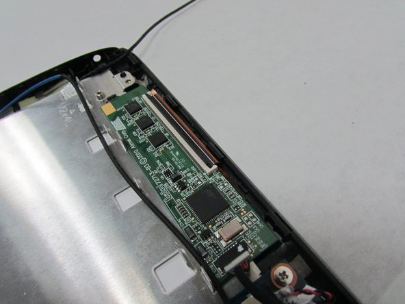
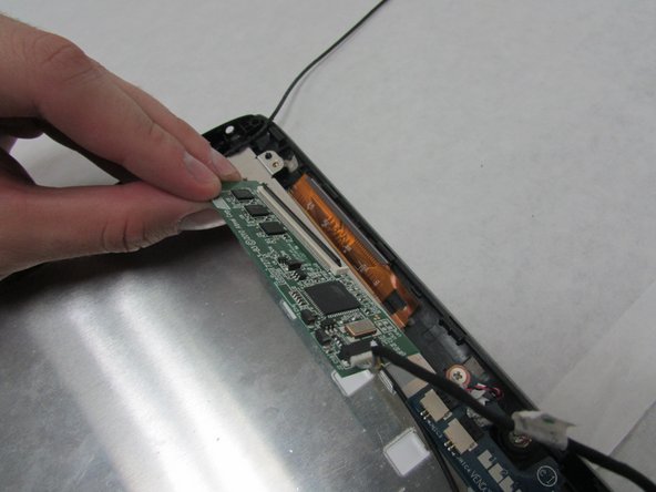
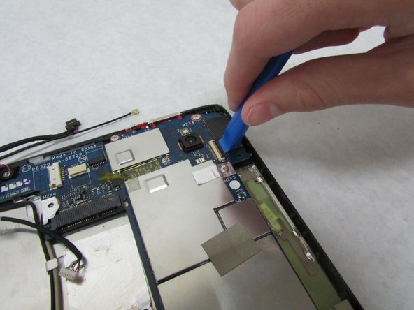
- Use the plastic opening tool to flip up the locking mechanism for the wide, white port for the thin, orange-brown touchscreen cable just above the charging port.
- Remove the touchscreen board.
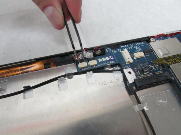
- In this step, be careful not to squeeze too hard or scratch the motherboard.
- Use the angled tweezers to disconnect two microphone connectors, which are above the orange-brown touchscreen connector and next to the battery space.
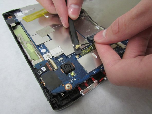
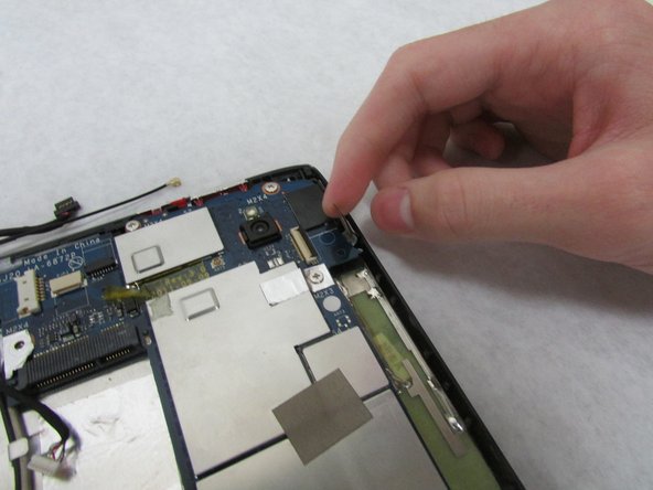
- Use the plastic opening tool to flip up the locking mechanism to the white front camera port just above the rear-facing camera.
- Disconnect the camera cable from the motherboard.
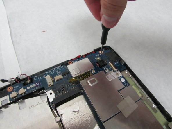
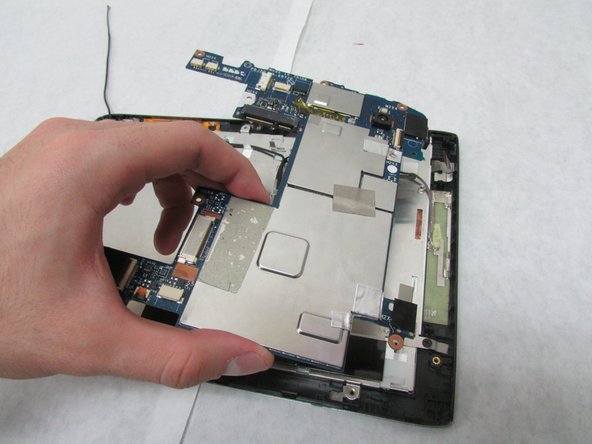
- Use a Phillips #1 screwdriver to unscrew the four 4.0 mm Phillips head screws holding the motherboard in place.
- Remove the motherboard.
- Remove the two microphones in the middle of the side opposite the docking port.
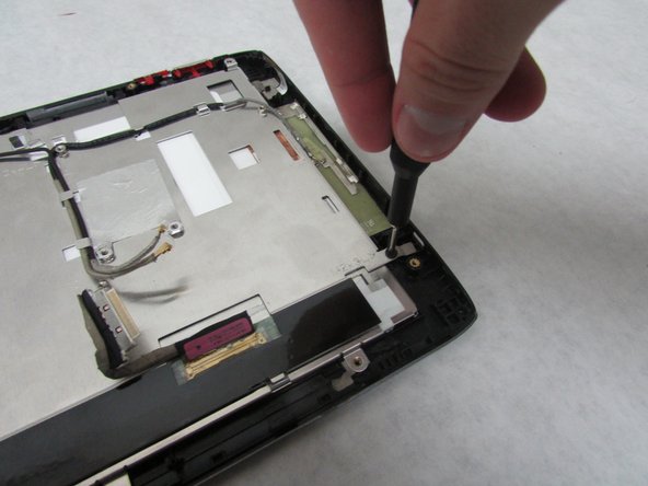
- Use the Phillips #1 screwdriver to unscrew the 3.0 mm Phillips head screw holding the thin metal plate to the device near the Micro-HDMI port.
- Use the Phillips #1 screwdriver to unscrew the 4.0 mm Phillips head screw near the orange-brown touchscreen cable.
- Move all wires off of the thin, metal plate.
- Remove the metal plate.
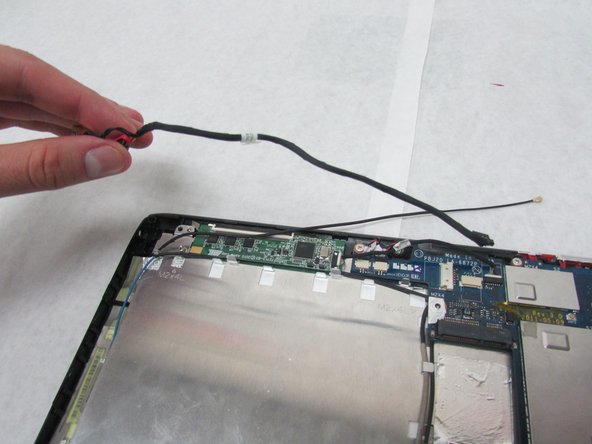
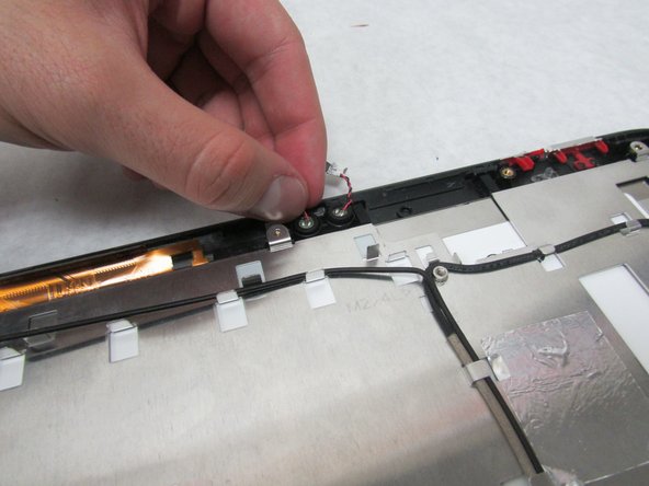
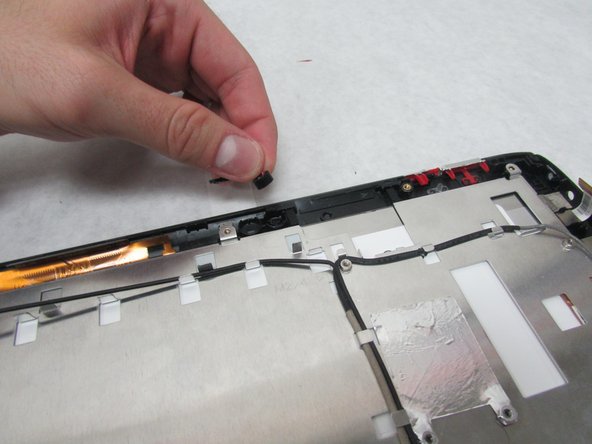
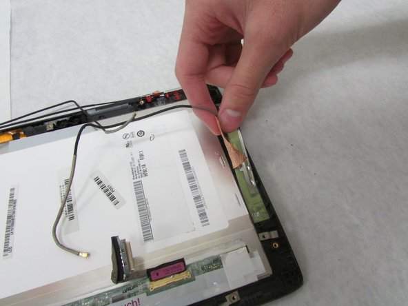
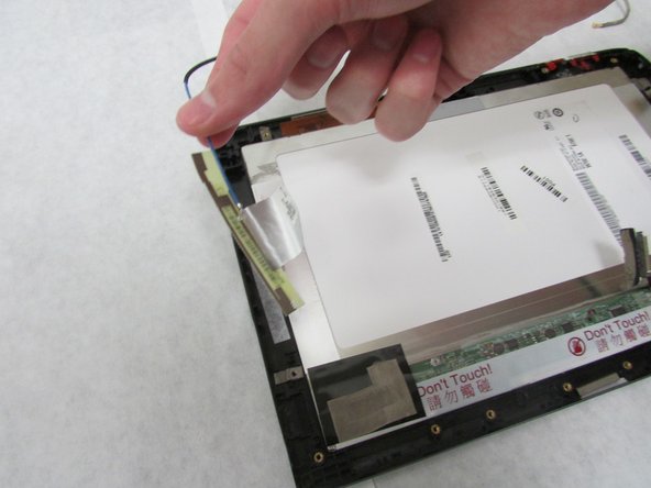
- The antennae in the next step are attached with adhesive.
- Remove the three antennae along the shorter sides of the device.
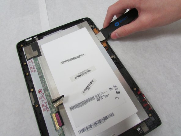
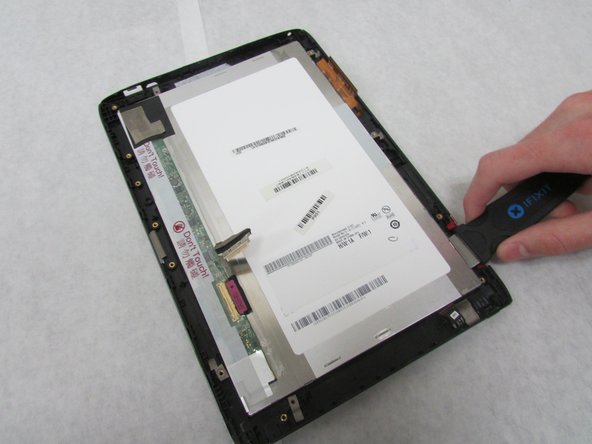
- Carefully insert the Jimmy between the display and the glass to break the glue seal.
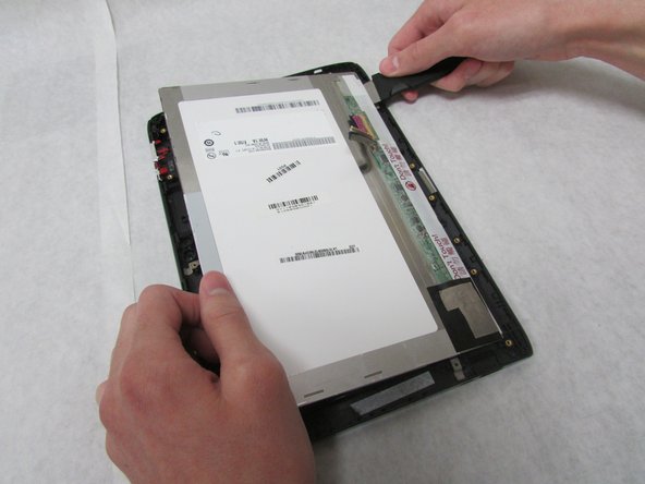
- Move the Jimmy all the way around the device.
- Continue moving the Jimmy around the device until the glue no longer holds the display in place.
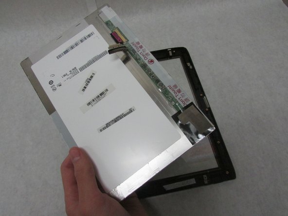
- Remove the display.
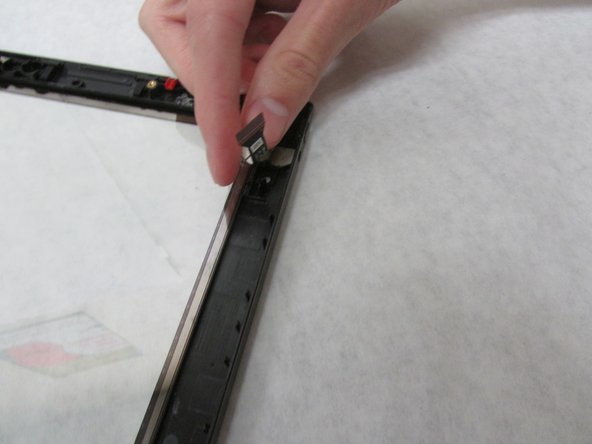
- Use the Jimmy to carefully remove the front camera from the front cover of the tablet.