GI Node with Pressure Transducer Assembly
ID: 125297
Description: Learn how to assemble a height adjustable GI...
Steps:
- open Anaconda Navigator
- launch Spyder
- click 'Open File' and select "node_builder.py" under "\Documents\anvil"
- click the 'Run' button
- visit this link to get started: Node Builder
- the slits along the 5-ft, 2-inch pipe are cut in the machine shop
- Using the table saw, cut the 1.5-inch pipe to be 6 inches long.
- The enclosure should have the standard node holes for the solar gland and solar panel attachment.
- The large hole is a 2-inch diameter hole. This is larger than the standard node enclosure. The machine shop will cut these holes.
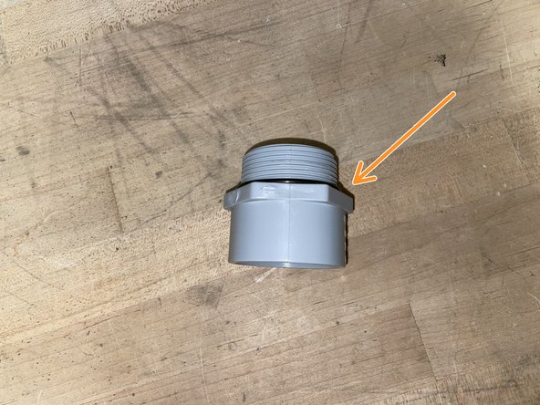
- Obtain a PVC conduit, o-ring, and a metal locknut
- Place o-ring on the threads of the PVC conduit (to ensure the enclosure is sealed from the outside)
- Insert the pipe fitting, screwing on the metal ring on the inside.
- Obtain the solar panel extension cable.
- Cover the connection between the solar panel wire and the extension cable with the heat-shrink tubing.
- Then, use a heat gun to shrink the tubing, creating a water-tight seal around the connection.
- Trim the solar panel extension wire so there is approximately 20 inches of wire from the connection point.
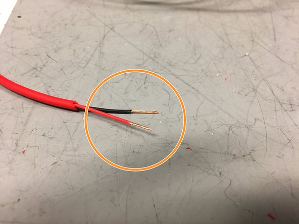
- Strip the wires as shown.
- Twist the ends of the wires.
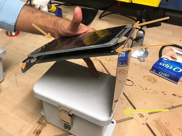
- Attach the solar panel onto the metal plate.
- Using screws and a screw driver, screw the solar panel into these holes. Now that the solar panel is attached to the metal plate, attach the metal plate onto the lid of the enclosure.
- Note: the tall side of the metal plate should be on the same side of the enclosure as the holes for the ultrasonic sensor and cable glands.
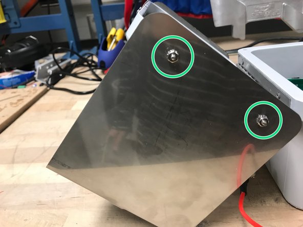
- The screws and nuts should be screwed in this matter in the holes on the sides of the box lid (meaning the nut is on the outside).
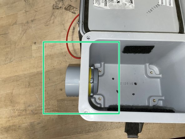
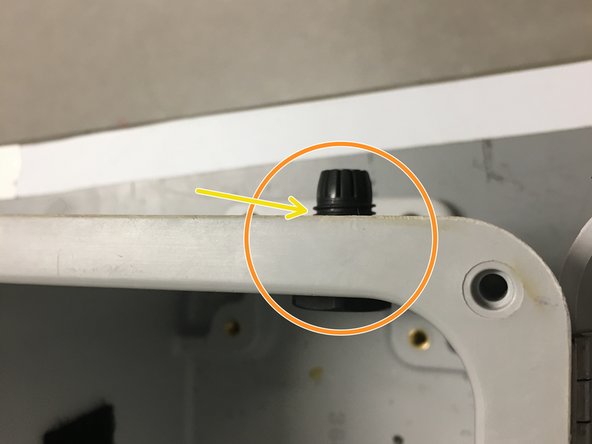
- Obtain a cable gland.
- Screw the cable gland into the wall of the enclosure, through the small hole, as shown.
- Place an o-ring between the cable gland and outer-wall of the enclosure.
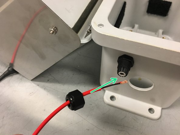
- Insert the solar panel extension wire into the cable gland as shown, leaving approximately 8 inches of wire inside the enclosure.
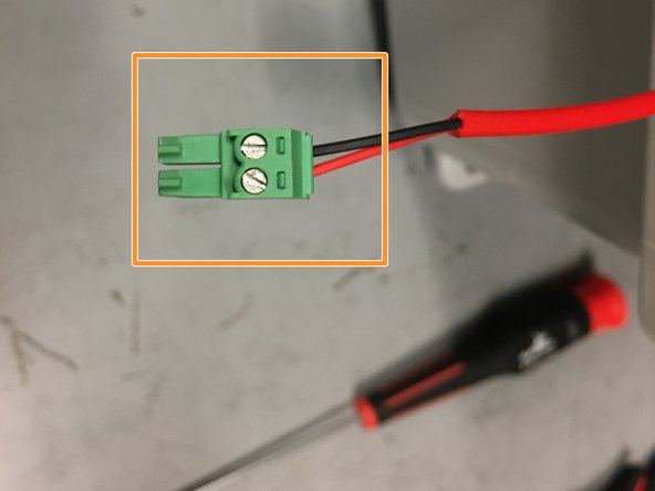
- Obtain a plugable header and ensure the ends of the wires are twisted.
- Screw the wires into the plugable header as shown in the picture.
- Note: hand tight is just right.
- If the pressure transducer wire is already prepped, skip ahead to step 14
- Obtain wire cutters.
- Obtain the pressure transducer for measuring infiltration.
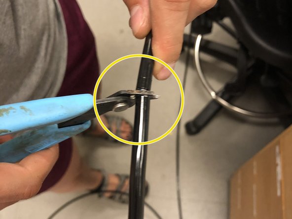
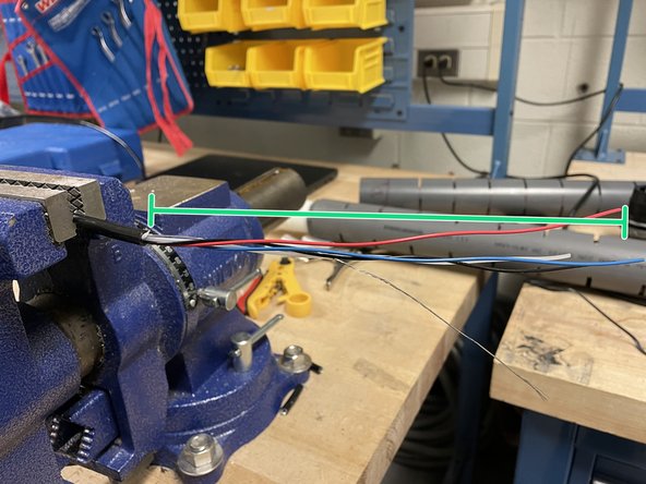
- Use coax cable cutters to cut the thick black outer cable at 75 inches from the end of the grey cylinder.
- Use wire cutters to cut through the inner wires.
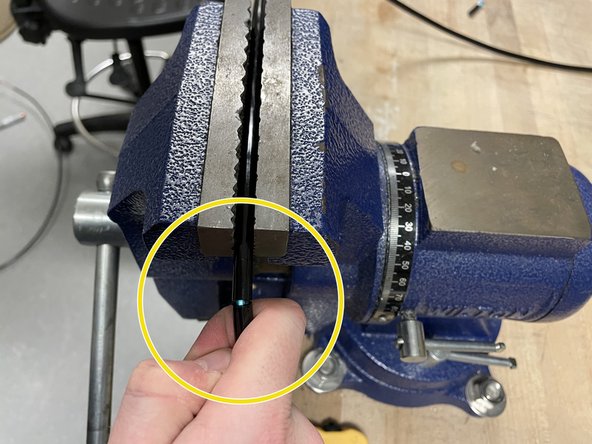
- Secure the pressure transducer wire in the workbench vise.
- Use the coaxial cable cutters to remove about 1.5 inches of the thick black shielding.
- Be careful not to break or cut the other wires (the silver wire is especially fragile)!
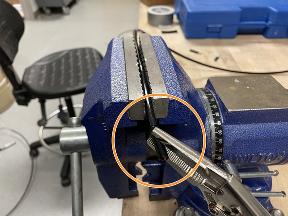
- Use your fingers to gently bend the wire along the line you cut. This should help separate the two segments of black shielding.
- Use pliers or vise grips to twist/pry off the black cable shielding.
- Continue stripping off an inch or so at a time until you have stripped off 6-8 inches of black shielding.
- Use wire cutters to cut the blue wire and plastic strips with every piece of black shielding that's removed (will make it easier to remove shielding as you go on).
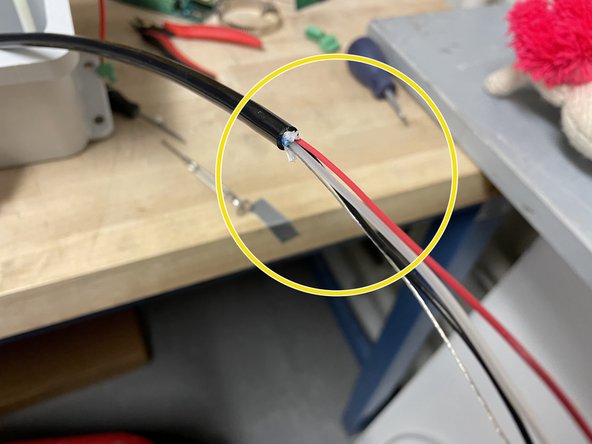
- Cut about 3-4'' off of the red sensor wire before stripping. This will allow all wires to be aligned once voltage regulator and additional wires are soldered on (Step 20).
- Use wire strippers to strip off about 1/4 inch off of the black and red wires.
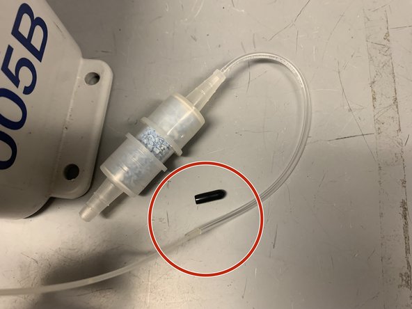
- The stripped wire should now look like this.
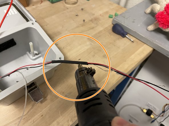
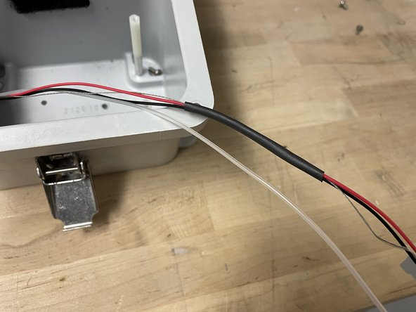
- Obtain a 4-5 inch piece of heat shrink tubing, and slide it over the wires – excluding the clear tube
- Gently apply heat using the heat-gun to shrink the heat shrink, making sure to avoid melting the clear tube.
- Wave the heat-gun in a back and forth motion to avoid overheating/melting the wires inside.
- Obtain 1.5-inch pipe from step 2
- Apply purple PVC primer to the outside of the PVC pipe and the inside of the conduit fitting. Apply PVC cement over the primed areas. Work quickly
- Insert the PVC pipe in the fitting as far as it will go, twisting about a quarter turn. Hold the pipe in place for about 30 seconds.
- Complete this step outside or in a well-ventilated area.
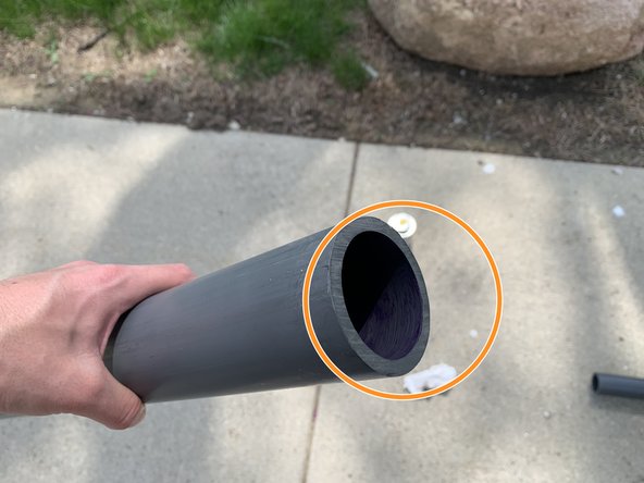
- Obtain the long, notched 2-inch PVC pipe
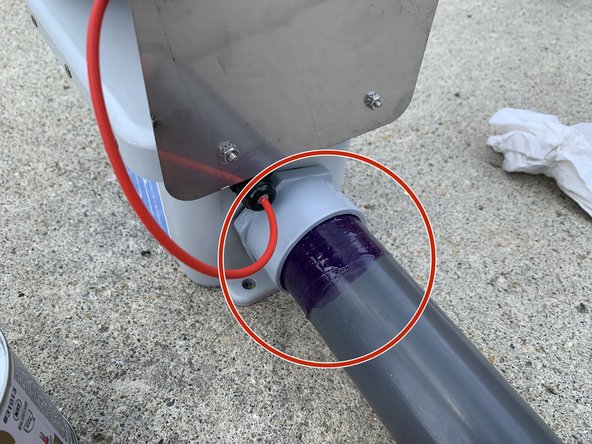
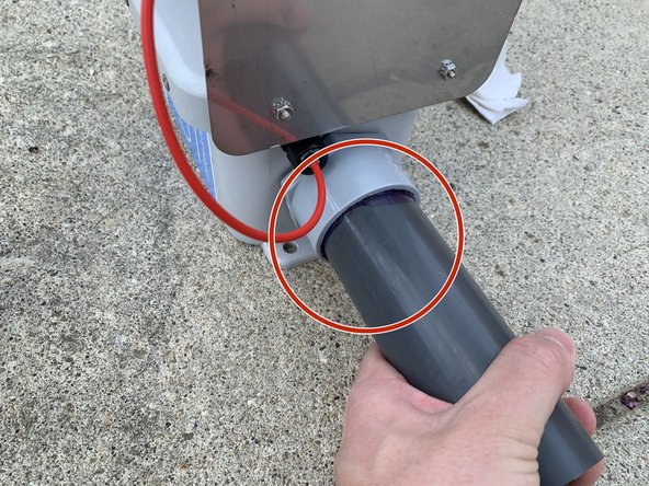
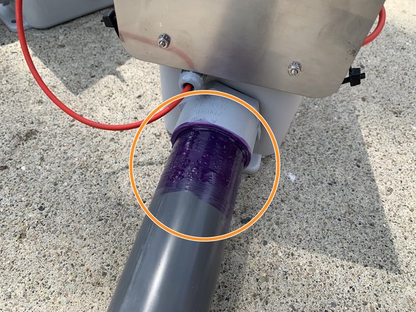
- Coat 2 to 3 inches of the 1.5-inch PVC pipe (closest to the housing) and the inside of the long 2-inch PVC pipe with PVC primer. Coat both of these primed areas with PVC cement.
- Insert the 1.5-inch PVC piece (connected to the housing) inside of the 2-inch PVC until the conduit fitting touches the 2-inch pipe. Twist a quarter turn while inserting and hold in place for 30 seconds.
- Complete this step outside or in a well ventilated area.
- Obtain a foot valve, remove the internal spring and recycle it.
- Trim the foot valve with a saw, leaving the 1.25 inch and 1.5 inch sections (allowing it to screw into the pipe bushing).
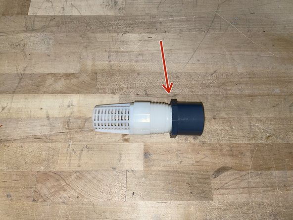
- Obtain a foot valve and 1.5 inch pipe fitting
- Screw foot valve onto pipe fitting as shown
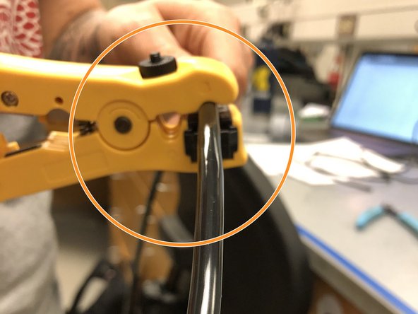
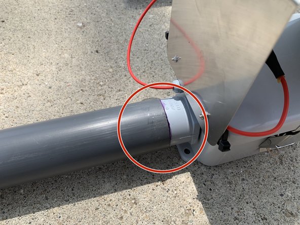
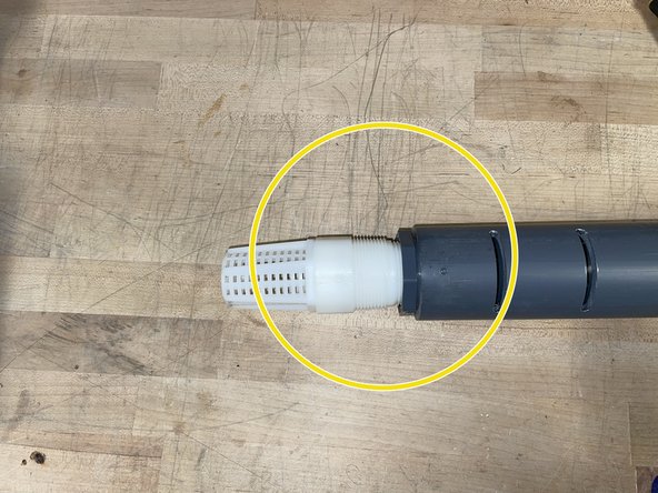
- Slide the pipe fitting into the 2-inch pipe as far as you can. Make sure to use the opening on the end with the slits
- Thread the pressure transducer wire into the 2-inch pipe. Make sure the end of the transducer sits at the bottom of the foot valve.
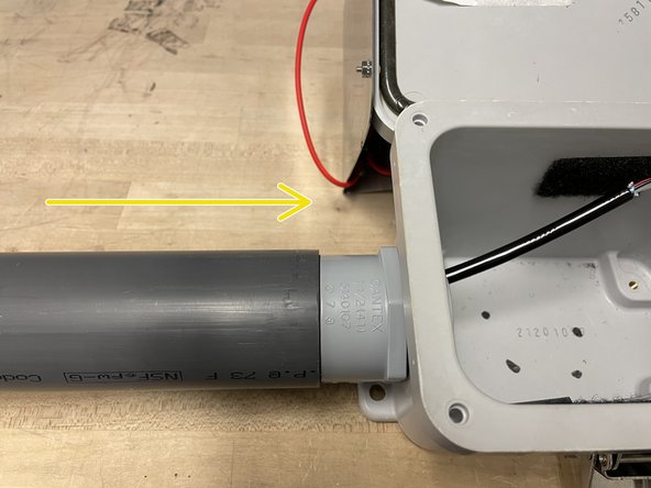
- Slide the 2-inch pipe over the 1.5-inch pipe, threading the pressure transducer wire through the 1.5-inch pipe in the process
- The sensor wires should be inside the node now!
- Obtain a Pololu 12V step-up voltage regulator.
- Obtain a 4 inch long pieces of red and blue wire
- Solder the red power wire from the sensor into the VINthrough-hole (from the side without text)
- Solder the blue wire into the GND through-hole (from the side without text)
- Solder the red wire into the VOUT through-hole (from the side with text)
- Insert a 150-Ohm resistor the into terminal block as shown
- Insert the black data wire from the pressure transducer into the second leftmost slot (with one of the resistor prongs).
- Insert the silver ground wire and blue wire (from voltage regulator) into the leftmost slot (with the other resistor prong).
- Insert the red wire from the voltage regulator into the middle slot on the terminal block
- Note: Hand tight is just right.
- Tug on the wires. If any come out, try repositioning them and screwing them back into the terminal block
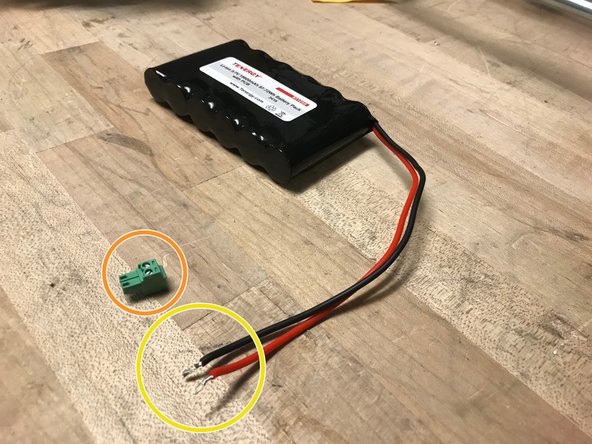
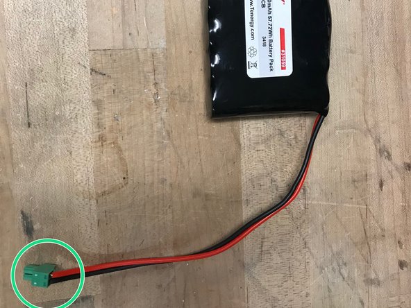
- Obtain lithium ion 3.7V battery.
- Obtain a 2-position block plug.
- Twist the wires of the battery so they fit nicely in the pluggable-header block.
- Screw the wires into the block plug.
- Note: hand tight is just right
- Add velcro with soft side inside the enclosure in the following places.
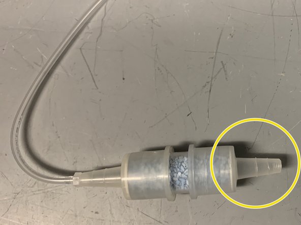
- Obtain a Steven's SDS desiccant cartridge
- Remove the yellow cap.
- Remove the black cap from the rubber tube. Push the plastic tube from the sensor into the rubber tube on the desiccant cartridge.
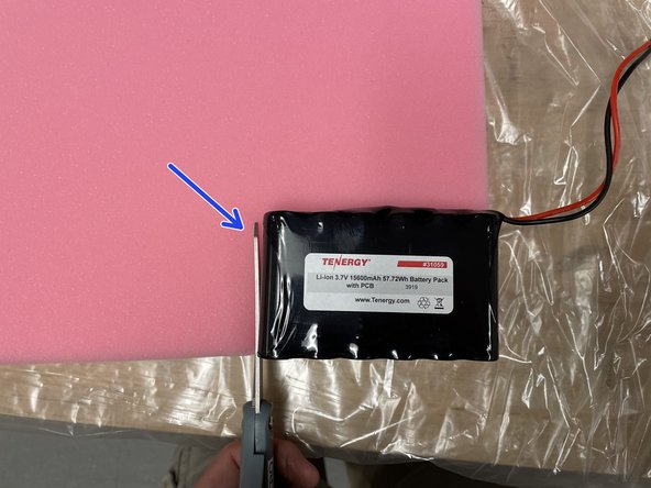
- Obtain one battery, 4 zip ties, foam, and a pair of scissors
- Cut out two battery-sized pieces of foam
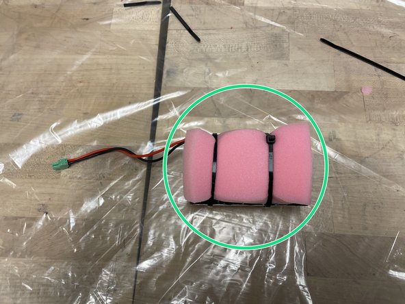
- Sandwich the battery between the two pieces of foam and secure it using the zip-ties. Connect the zip-ties to make two extra long zip-ties
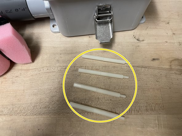
- Obtain a foam-wrapped battery from the previous step, and 8 standoffs
- Screw the standoffs together as shown, to make four 3-inch long standoffs
- Screw the standoffs into the enclosure, then place the battery vertically in-between the standoffs
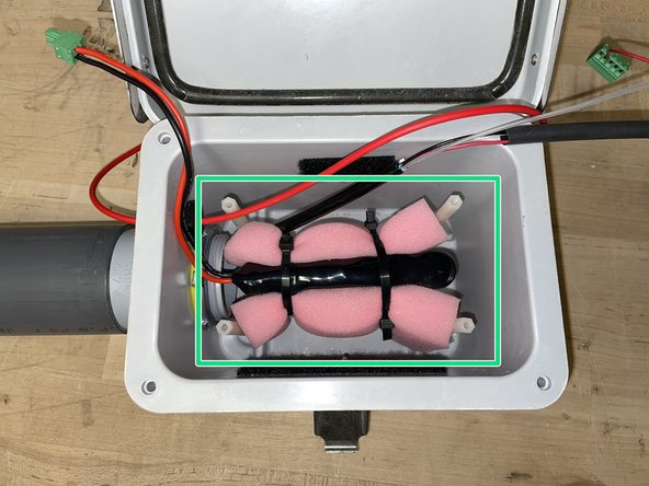
- Make sure the sensor wires and desiccant cartridge are secured inside the box.
- Make sure the battery is positioned so that its wires are on the sensor's side of the enclosure
- Obtain an antenna and GPS unit. Attach rough-sided velcro on the antenna and GPS as shown in the picture.
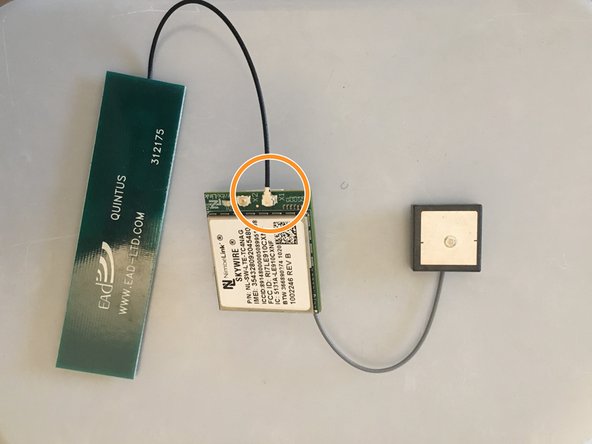
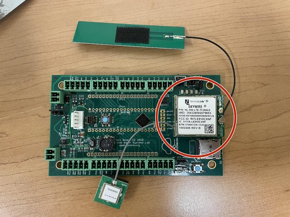
- Obtain the cell module (modem), GPS, and antenna
- Insert Super SIM card into cell module
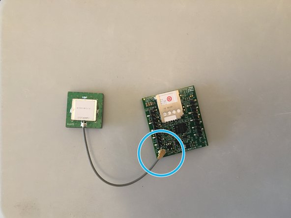
- Attach the GPS to the connection shown (grey wire)
- Attach the antenna to the connection shown (black wire)
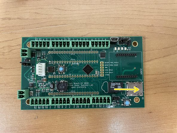
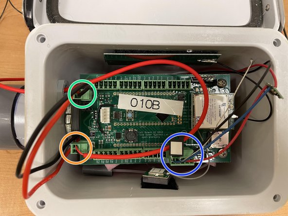
- Obtain Open-Storm board and place 4 jumpers in the spots shown
- Insert microSD card into board
- Attach the cellular module onto the sensor node board in the appropriate place
- Screw the board onto the standoffs
- Attach the gps and antennae to the velcro on the walls of the enclosure
- Ensure the board is oriented with the modem on the opposite side of sensor
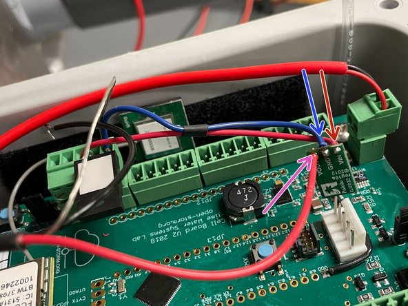
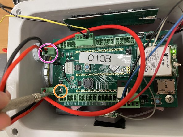
- Plug in the terminal block as shown. The silver wire should go to GND, the black data wire should go to P3.2, and the red power wire should go to P3.3
- Plug in the solar panel
- Plug in the battery
- save this step for later if the node isn't immediately going out for testing
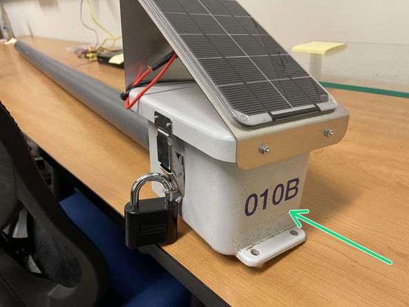
- Apply open-storm sticker to the side of the enclosure as shown
- Apply unique node ID sticker to the side of the enclosure as shown
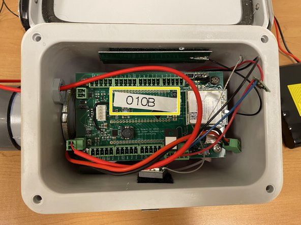
- Create a label of this unique node ID using the label maker, and stick it to the board as shown
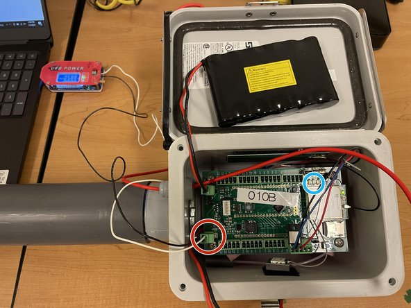
- Obtain USB power supply, plug into a laptop, and set output to 5.9V
- Check the voltage with a voltmeter (you may have to set the power supply to ~5.8V for the voltmeter to read 5.9V)
- Plug in the green terminal block from the power supply into the Open-Storm board solar port.
- Confirm the solar charge LED is off.
- Plug in a dead battery to the battery port. This step will not work with a charged battery
- CAREFULLY turn the silver potentiometer next to the charge controller IC with a small flathead screw driver until the charge light turns on.
- Although the screw has a phillip screw head, using a phillip screwdriver may damage the potentiometer. The hole in the center is too shallow for most screwdrivers. It is easier to use a flathead screwdriver!
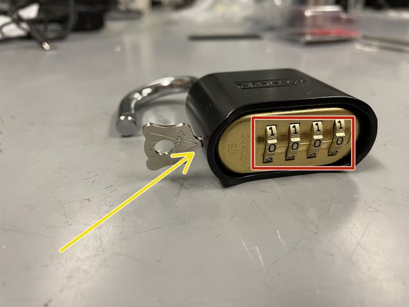
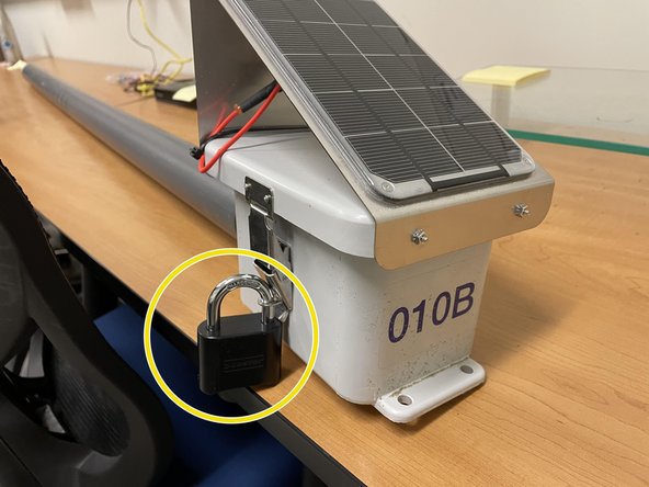
- obtain a master lock and a pair of scissors
- cut the lock and key out of the packaging
- set the lock to the default combination, 0-0-0-0, open the lock
- put the key into the lock and twist clockwise 90 degrees
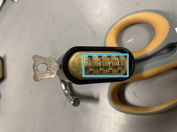
- while the key is still twisted, set the combo to 2-2-4-5
- remove the key, and the lock is ready to go
- this is what the node should look like on the inside
- attach the lock to the outside of the enclosure
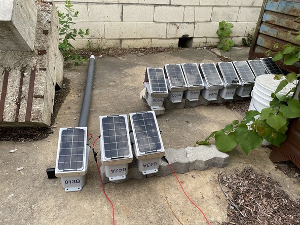
- return to Node Builder for instructions on how to drop off the node at the testing rack