Apple Disk II Floppy Disk Subsystem Teardown and Optical Drive Conversion
ID: 125341
Description:
Steps:
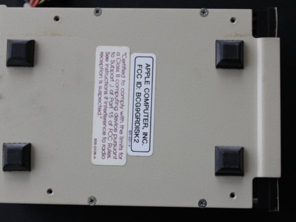
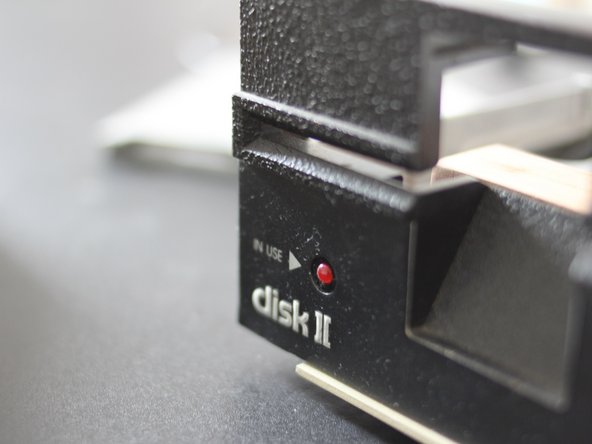
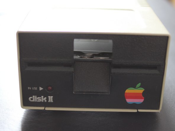
- The outside of the drive.
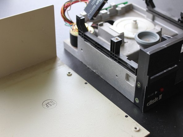
- Flip the drive over and remove the 4 Phillips screws underneath.
- Slide it towards the cable at back.
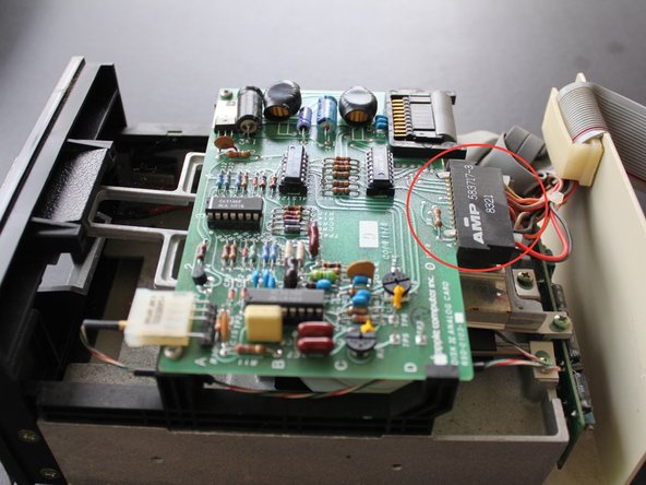
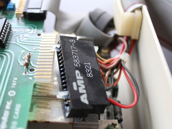
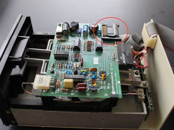
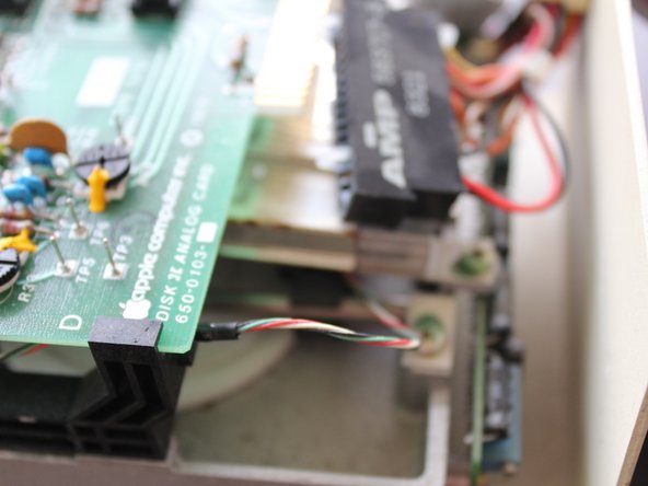
- Pull away from the board, not up
- Pull away from the board, not up
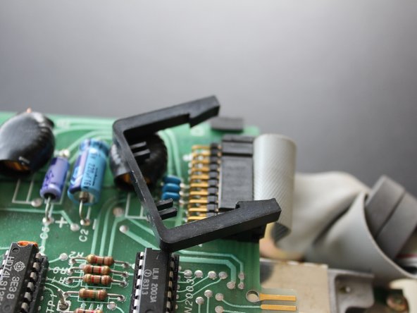
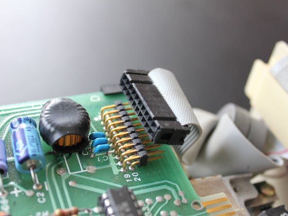
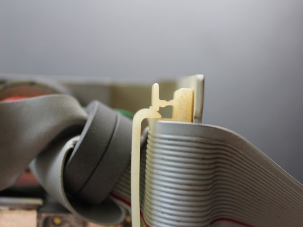
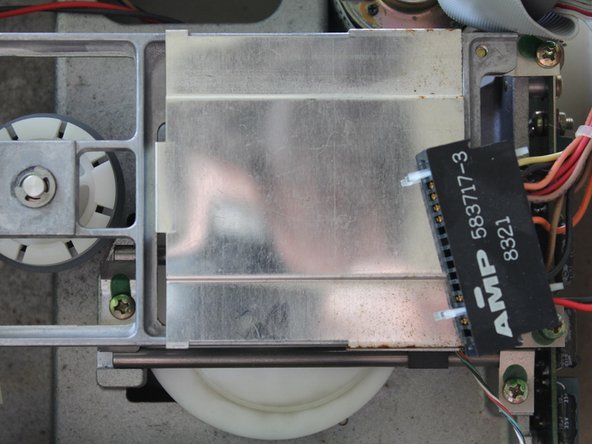
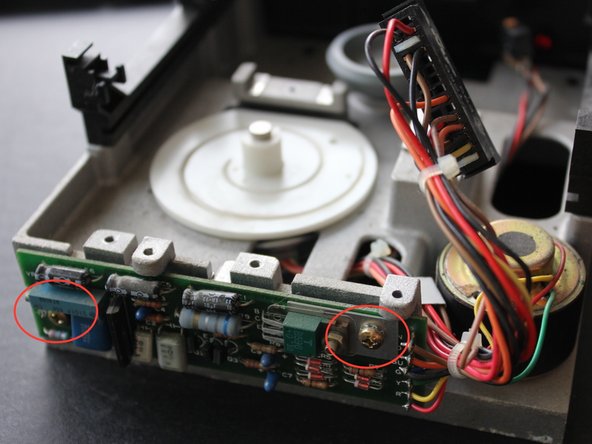
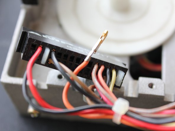
- First. remove the C retaining clip by gently pushing the sides away from the connector with your thumbs, then pull the cable away from the board, not up
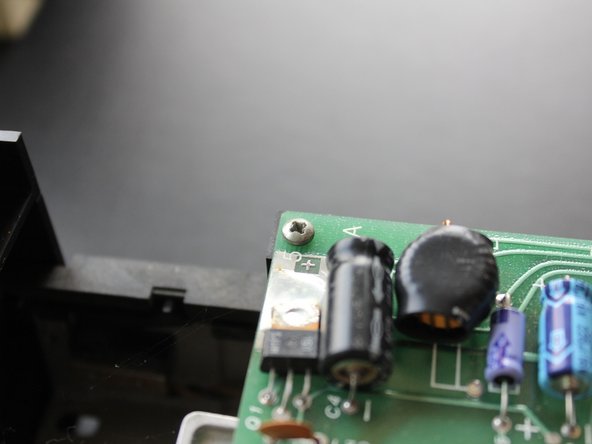
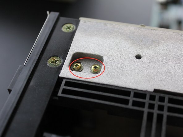
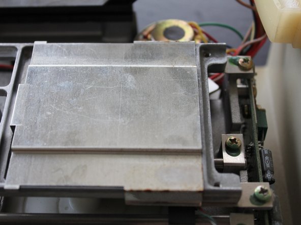
- Remove the 2 Phillips screws
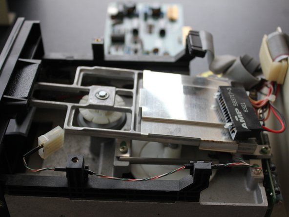
- Next, gently remove the board from the drive, minding the cable running beneath
- Insert wisdom here.
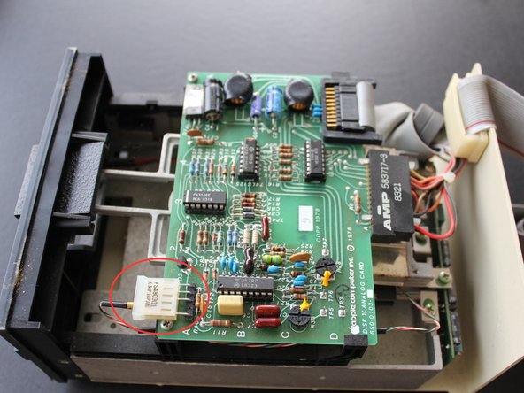
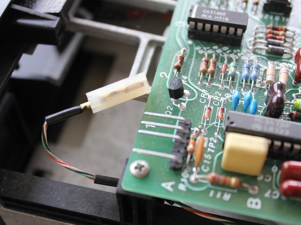
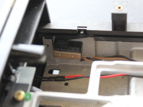
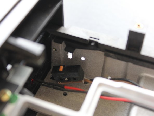
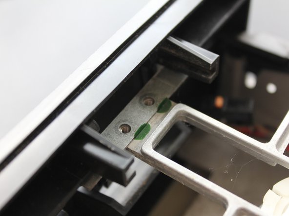
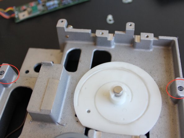
- Remove 2 Phillips screws holding in the sensor pictured
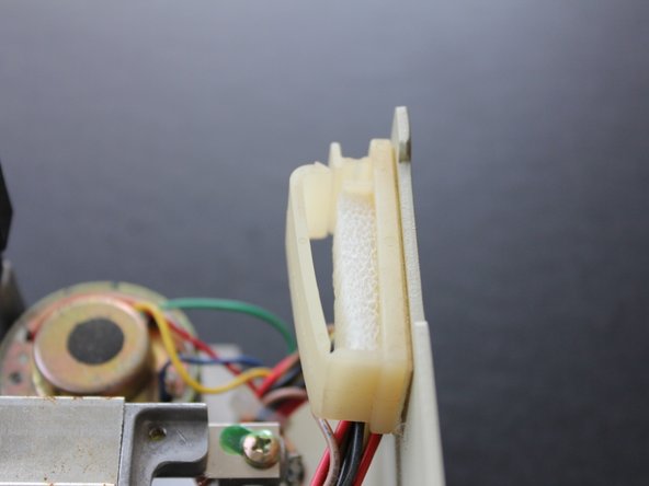
- Remove the grey cable from its retaining clip
- All screws pictured
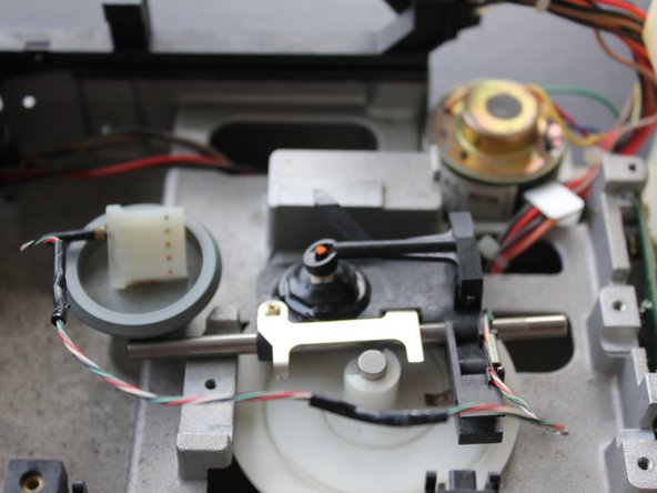
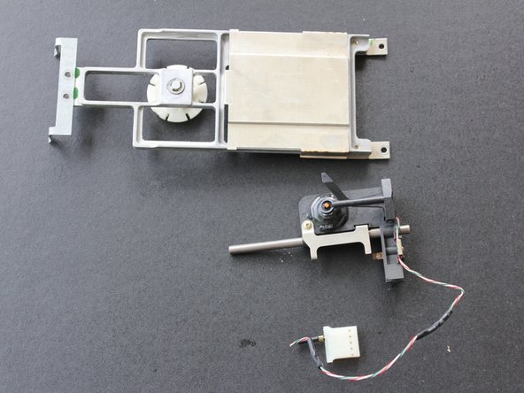
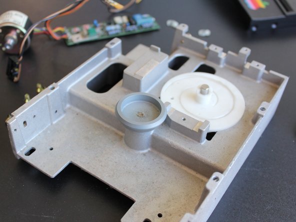
- As pictured, remove tray once screws are gone
- In addition to tray, lift out other components as pictured
- Insert wisdom here.
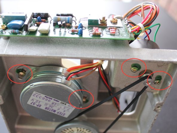
- 8 total, from sides and bottom
- Insert wisdom here.
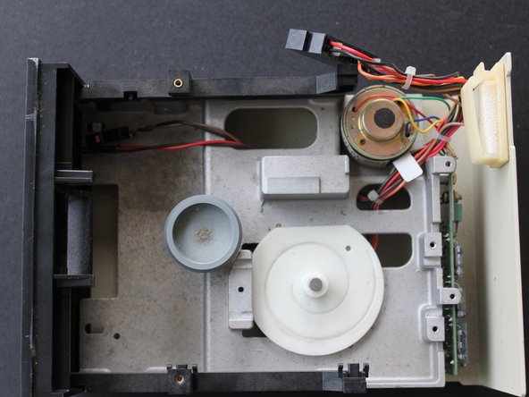
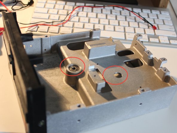
- As pictured, then remove all freed components
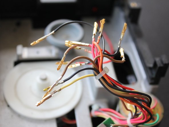
- Disconnect cables from black connector so motor and other components can be removed from chassis
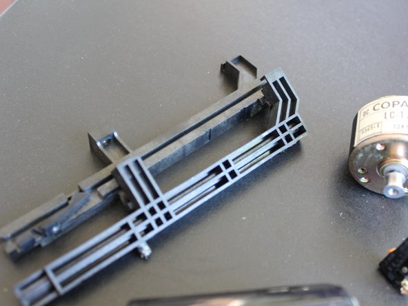
- Remove side rails by pulling up gently. Each rail has two plastic poles that sit in the body. In this attempt, each rail lost a pole that snapped off. Poles seemed to be glued down
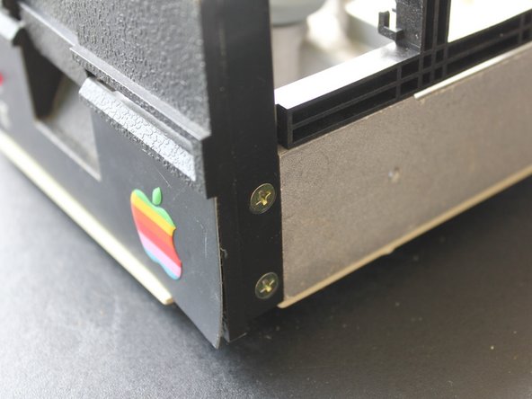
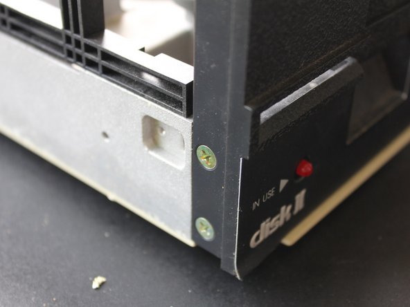
- Because the side screws were previously removed, the black front of the drive can come off. Our drive's LED was tested and worked, but was faint. Feel free to test yours first. If working, skip the next step
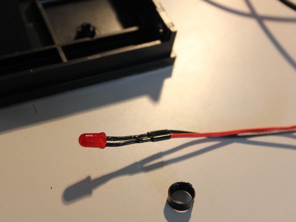
- Our LED was removed from the front case by removing the pictured ring with the help of a flathead screwdriver. Take your time so the front of the case isn't damaged and nothing besides the ring comes off
- Use pliers to remove the remaining components (see previous step)
- With the case stripped and a new LED purchased, the fun begins!
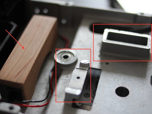
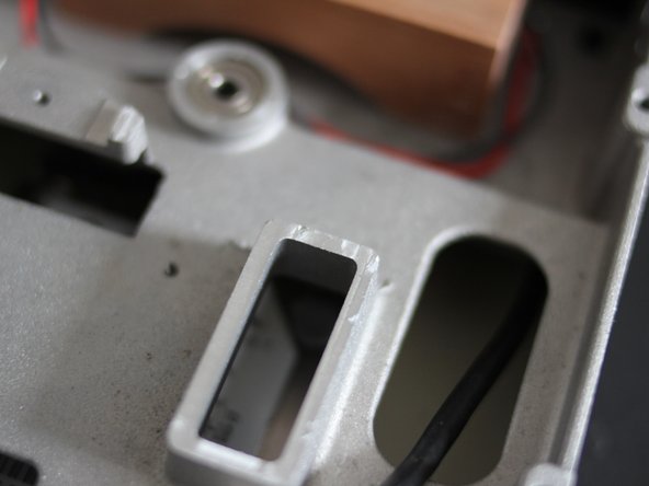
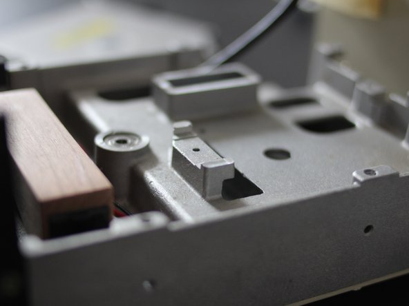
- The only major changes to the case are outlined in rectangles. The metal chassis was milled down to match the height of the bottom of the disk entry area on the black front plate. This lined up well with our Apple SuperDrive (pulled from a MacBook Pro)
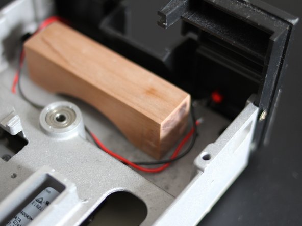
- The wood block was added for support underneath the SuperDrive
- The rails fit nicely around the SuperDrive when re-installed
- A new LED was purchased and soldered to the LED connector from a 2.5" USB to SATA board, and then inserted snugly into the front of the case (may not be necessary if your LED lights up well)
- With LED cabled routed, and 2.5" hard drive placed in cavity underneath
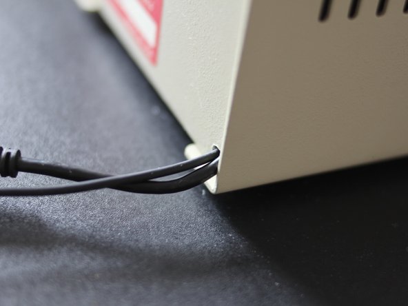
- Dremeled into the back plate for USB cables to route through
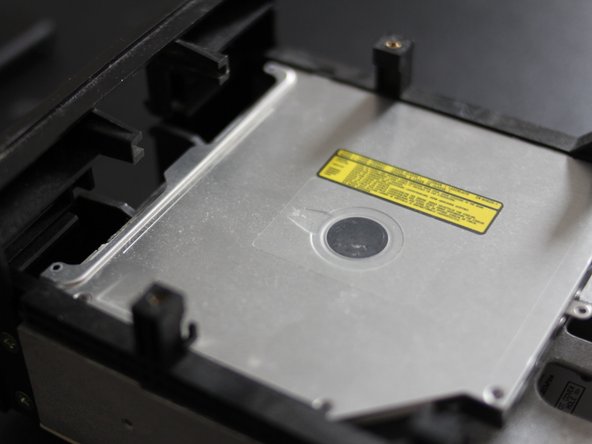
- Picture 1: optical drive installed into body
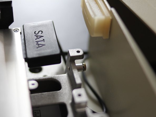
- Picture 2: SATA to USB cable for optical drive (plug and play on macOS. A right angle cable was purchased but a straight cable would be preferable due to the amount of space at the back, as pictured)
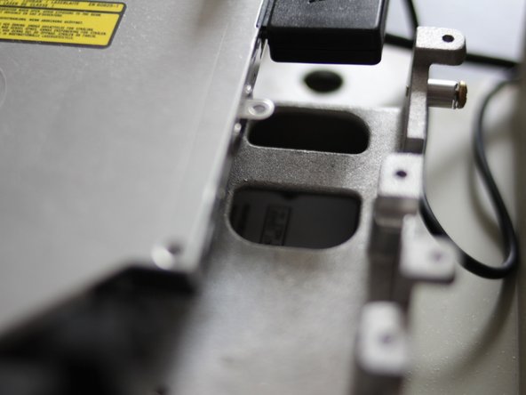
- Picture 3: hole to thread SATA to USB cable through for 2.5" hard drive
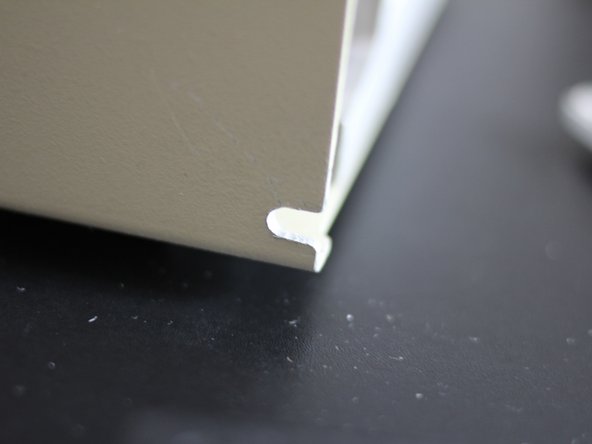
- The original 'latch' slides out easily without the original components, so it was left out
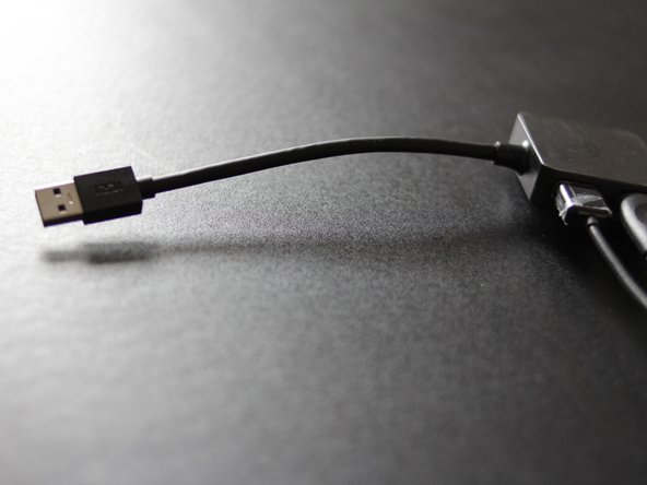
- Run out of case to 4-port USB adaptor (possible to install inside case if a hole could be cut out)
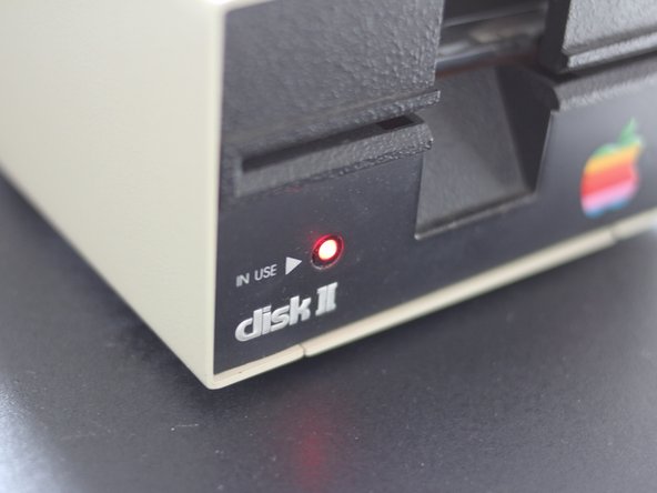
- Flashes on SATA data read from hard drive
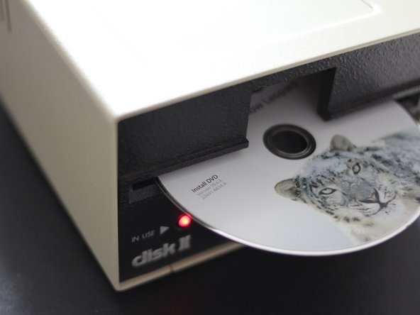
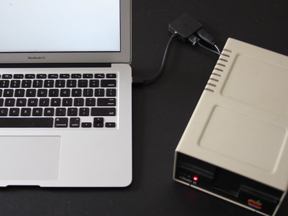
- With the drive connected to a Mac over USB (hub is enough to power both OD and SATA drive over one cable) we can insert and eject DVDs with ease!
- To re-assemble, replace all body Phillips screws
- Enjoy your vintage look with up to date tech!