Nintendo Switch Pro Controller Buttons / D-Pad Replacement
ID: 127790
Description: The Nintendo Switch Pro controller’s buttons...
Steps:
- Flip the controller over so the model stickers face the ceiling.
- Use a JIS #00 screwdriver to remove the two black 8.4 mm screws that secure the handles, located at the ends of the handles.
- Carefully remove the handle covers by pulling them away from the main body.
- Use a JIS #00 screwdriver to remove the four silver 6.8 mm screws that secure the clear back plastic cover.
- Carefully pry away the clear plastic cover using your fingernail.
- Remove the clear plastic cover.
- Remove the lithium-ion battery by using a fingernail or plastic opening tool to pry it up on the left side.
- Only a small amount of force is needed.
- Use a Phillips #1 screwdriver to remove the five 5 mm screws from the back of the controller.
- The two case screws above the handgrips and the single case screw below the battery bay have a shallow seat. These three screws can be easily removed.
- The two case screws adjacent to the ZR and ZL shoulder buttons have a deep seat. Use an extension or a narrow PH1 Phillips screwdriver with a longer shaft to reach these screws.
- There's an adhesive pad located in the center of each handle. It will require a bit of force to pry away the front cover, but be mindful of the attached ribbon cable.
- Delicately take off the plastic cover from the controller.
- Don't completely remove the front cover just yet, as it's still attached to the motherboard via a white ribbon cable.
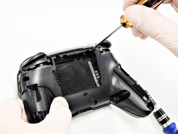
- Use the tip of an opening pick to open the black flap of the ZIF connector by pushing it upwards.
- Use your fingers or a pair of blunt nose tweezers to disconnect the interconnect cable from its connector.
- Remove the front case.
- Remove the two 6.8 mm-long screws on the top circuit board using a Phillips screwdriver.
- Use a spudger to flip up the locking tab on the ZIF connector.
- Remove the black ribbon cable from its connector.
- Only a small amount of force should be needed to remove the ribbon cable.
- Remove the trigger buttons from the plastic cover.
- Use a Phillips screwdriver to remove the two 5 mm-long screw securing the circuit board.
- Remove the circuit board.
- Use your fingers or a pair of tweezers to remove the button(s) you wish to replace.