Nintendo Switch Left Joy-Con Shell Replacement
ID: 130378
Description: This guide will help you replace the shell of...
Steps:
- Start by unscrewing the four Tri-wing Y00 screws from the back panel.
- Keep the screws somewhere safe and organized.
- Insert an opening pick into the seam at the bottom edge of the controller (opposite the L and ZL buttons).
- Slowly slide the flat edge of your opening pick up the side of the Joy-Con, opposite from the rail.
- With the charging rail facing away from you, open the Joy-Con like a laptop.
- Do not fully remove the back panel yet; there are still two ribbon cables connecting the charging rail to the motherboard.
- Gently pry the battery connector straight up from its socket on the motherboard using a plastic spudger (avoid metal ones to reduce the risk of shorting components). This will keep the Joy-Con from powering on during the repair.
- Use caution while working around the rumble module's cable which runs in the vicinity of the battery connector.
- When handling electronics and/or batteries, it's a good idea to wear at least an anti-static bracelet.
- Insert a spudger between the battery and the Joy-Con housing.
- Gently pry out the battery.
- The battery is lightly taped in place.
- Be careful not to deform, puncture, or damage the battery.
- Remove the three 3½mm golden Phillips #00 screws from the mid-frame.
- Carefully flip the mid-frame over, away from the motherboard, as if you were turning the page of a book.
- The flex cables are extremely fragile. It is advised to use non-sharp tweezers rather than bare hands.
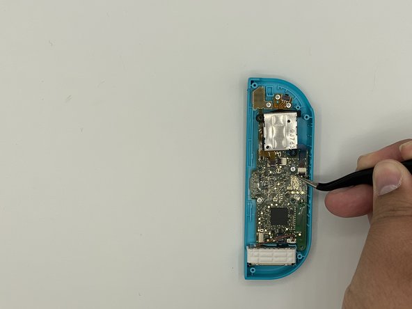
- Use tweezers to flip the ZIF connector lock opposite the cable.
- The ZL button is locked in place by a small ZIF connector on the motherboard.
- Use tweezers to gently pull the ZL button flex cable out of its ZIF connector socket. The mid-frame is now disconnected and can be removed.
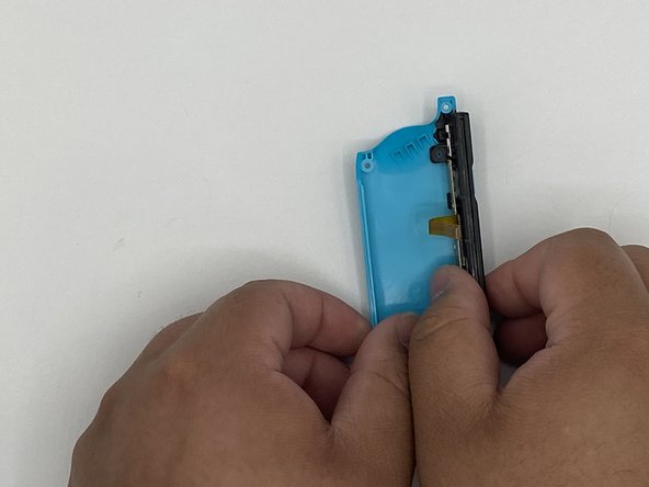
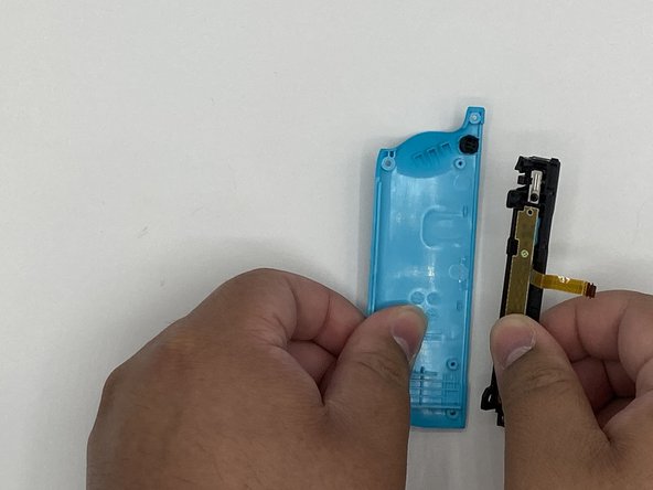
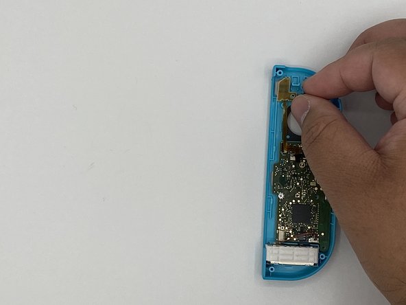
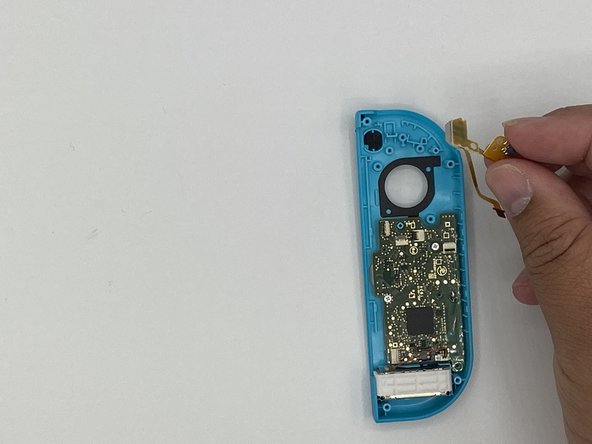
- Unlock the rail's top ZIF connector and then disconnect the cable.
- Unlock the rail's bottom ZIF connector and disconnect the cable. You can now remove the rail from the back frame.
- Remove the L button and its spring.
- Be careful because the spring tends to fling away.
- Remove the screw holding the rail in place. Remove the rail from the back frame and set it off to the side.
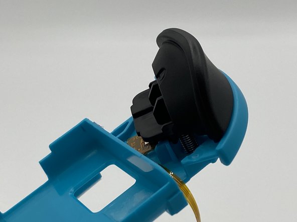
- Remove the latch button and set it off to the side.
- Depress the latch underneath the trigger using tweezers. Gently pry the trigger off.
- Make sure to note the position of the two springs under the trigger as they will need to go back in the same spot on the new mid-frame.
- Remove the screw holding the circuit board for the trigger in place.
- Remove the circuit board.
- Remove the screws holding the analog stick in place.
- The top-left screw is covered by the L button's flex cable.
- Unlock the ZIF connector and remove the flex cable using tweezers.
- Remove the analog stick.
- Remove the screws holding the flex circuit (marked by a red circle) for the minus and L buttons.
- Remove the flex circuit.
- Remove the minus button.
- There will be a silicone membrane covering the minus button. Make sure to put it back over the minus button during reassembly.
- Remove the screws holding the motherboard in place.
- Using a spudger, gently pry the rumble module out of its housing.
- Remove the rumble module and the motherboard.
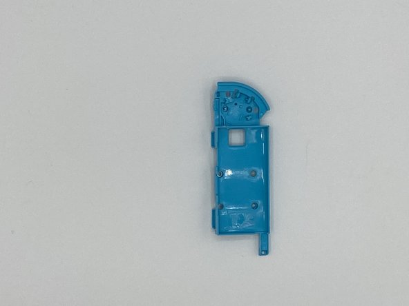
- Remove the remaining five buttons from the shell.