GFCI Outlet Replacement
ID: 130406
Description: The National Electrical Code and National Fire...
Steps:
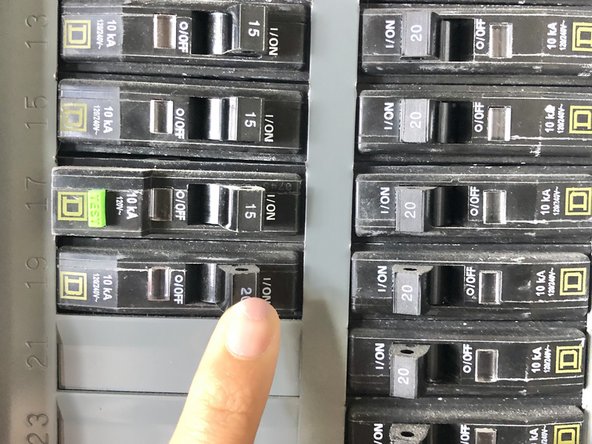
- Find the breaker box and switch off the breaker that is labelled "GFCI receptacle"
- If not sure, switch off all breakers.
- Push the "Test" button once.
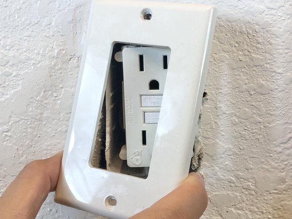
- Using #2 flat-head screwdriver, remove the outlet cover by unscrewing the top and bottom screw.
- Using #2 flat-head screwdriver, unscrew the top and bottom screws holding the outlet onto the wall.
- Pull the outlet out from the interior outlet box, exposing the wires that are inside the electrical box.
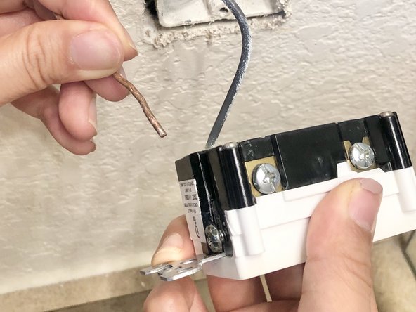
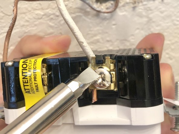
- Remove the 5mm Phillips #1 screw for the white wire (neutral wire) and free the wire from outlet.
- The white wire (neutral wire) is typically located on the left side of the outlet.
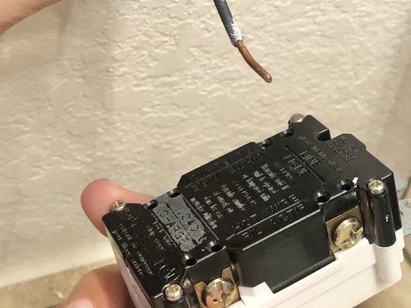
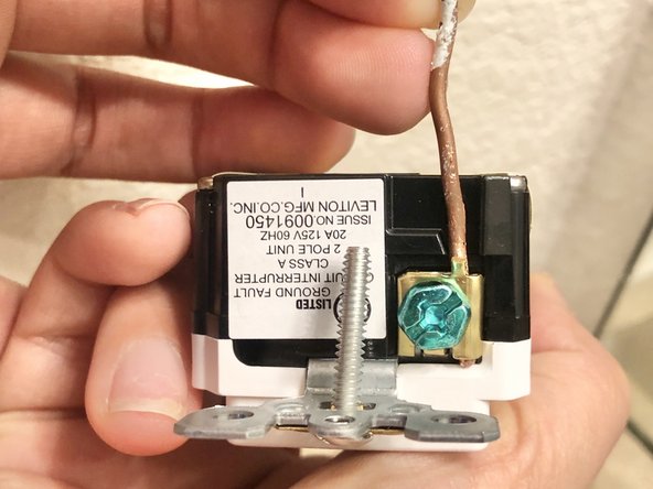
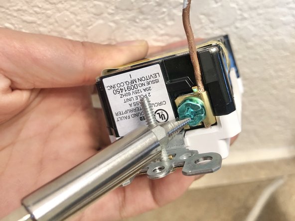
- Remove the 5mm Philips #1 screw for the copper wire (ground wire) and free it from the outlet
- The copper wire (ground wire) is typically located on the bottom of the outlet.
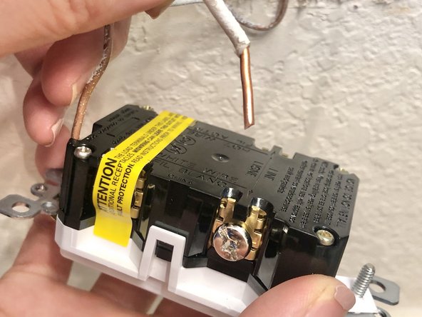
- Remove the 5mm Phillips #1 screw for the grey wire (hot wire) and free it from the outlet.
- The grey wire (hot wire) is typically located on right side of the outlet.
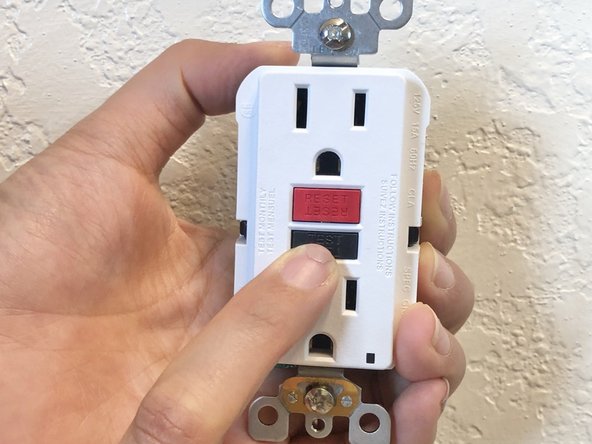
- Push the "TEST" button on the new outlet.
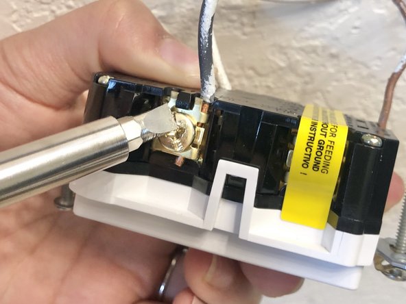
- Retrieve the copper wire (ground wire) and slip it into the copper hole which is attached with the green screw located bottom of the outlet.
- Tighten the screw down with flat-head screwdriver.
- Make sure to use the original equipped screws that come with the new GCIF outlet.
- Locate a hole that is labeded white wire.
- Slip in the white wire (neutral wire) into the hole located on left side of the outlet.
- Tighten the screw down
- The white wire (neutral wire) is typically located on left side of the outlet.
- If there are two holes available, use the bottom hole.
- Locate a hole that is "HOT WIRE".
- Slip in the grey wire (hot wire) into the hole located right side of the outlet.
- Tighten the screw down.
- If there are two holes available, use the bottom hole.
- Push the outlet and wires back into the wall.
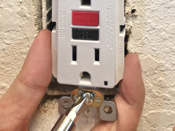
- Tighten the screws on the top and bottom tabs, positioning the outlet so that it is vertically straight.
- Make sure to use the original equipped screws that come with the new GFCI outlet.
- Install the outlet cover by tighten the top and bottom screws.
- Turn on all the breakers that you turned off in step 1.
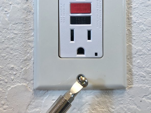
- Push in the "RESET" button until you hear "click" sound.
- If no "click" sound, check and make sure that the correct breaker is switched to on position.
- If still not getting "click" sound, start over from step 1 and make sure all three wires are inserted fully into the correct holes.
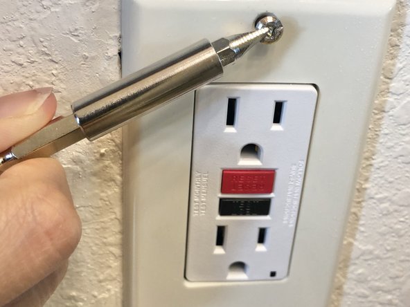
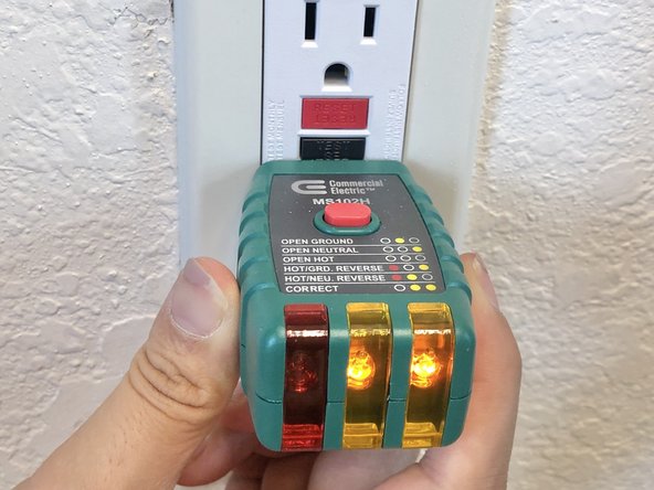
- Plug in the circuit tester into one of the plug.
- Two yellow led lights will light up if the new outlet is installed correctly.
- If two yellow LED lights does not light up, go back to step 1 and make sure the wires are fully inserted in the correct spots.
- Congratulations, enjoy your functional GFCI outlet receptacle!