Anker Soundcore A3201 Speaker Replacement
ID: 130582
Description: For our Fast Fix Project, we wish to document...
Steps:
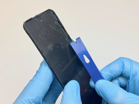
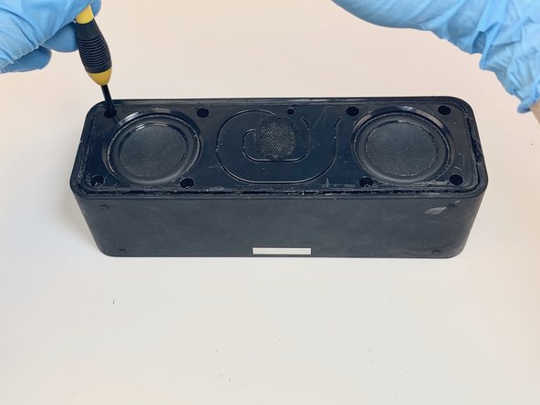
- The grille is held on by a small layer of silicone sealant.
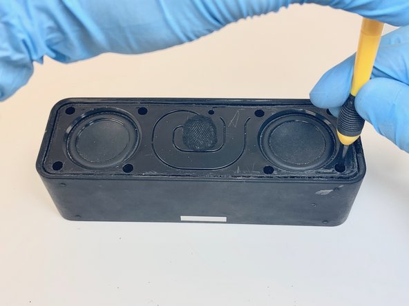
- Gently pry on each edge of the front grill with a plastic opening tool.
- Using the pry tool, start at one side and lift and remove the front grille.
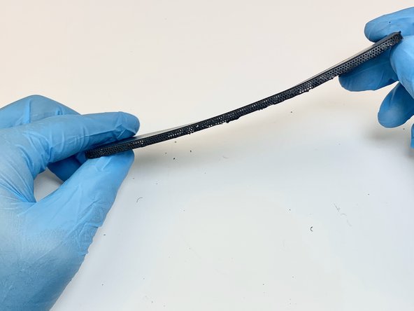
- It is possible to bend the grille, it is okay if it is slightly bent. For proper reassembly use gently force when removing the grille and be cautious to not damage it.
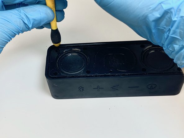
- After removing the grille there will be silicone residue left over on the speaker housing.
- Use the plastic opening tool to gently remove the remaining silicone.
- Do not scratch or damage the speaker housing when removing the excess silicone sealant.
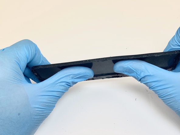
- After removing the grille there will be silicone residue left over on the inside and edges of the grille.
- Use the plastic opening tool to gently scrape and remove the excess silicone.
- Do not damage the grille, by scraping or bending it as it is needed for reassembly.
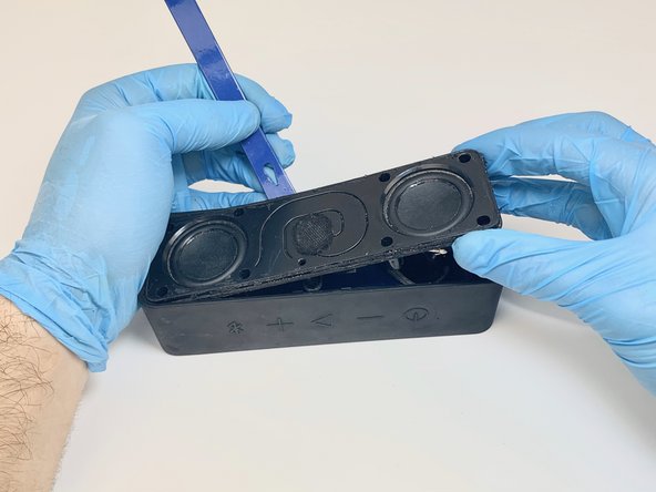
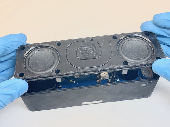
- After removing the grille the speaker housing and the two internal speakers are visible. This housing is holding the two internal speakers.
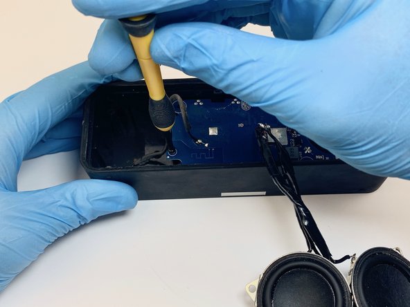
- Remove the eight 2mm screws from the speaker housing using a Phillips #1 screwdriver.
- After removing the eight 2mm screws the housing is free to be removed.
- Using the plastic opening tool, gently lift all sides of the housing.
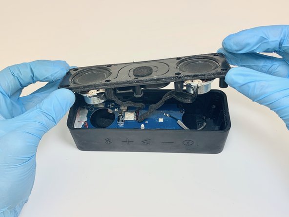
- The speakers are connected to the motherboard via two main connections directly under the middle of the speaker housing.
- Be careful to not pull on or push the wires when removing the speaker housing.
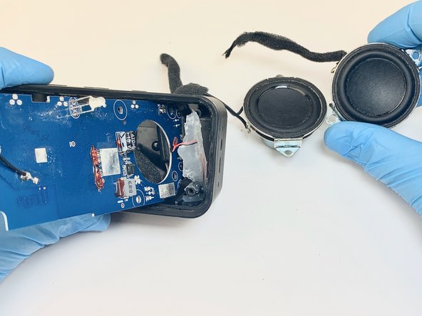
- After removing the speaker housing, the bottom of the internal speakers and motherboard is visible.
- Be careful to not pull or damage the speaker wires or motherboard.
- The speakers are still connected to the speaker housing and the motherboard. The speaker housing will not be able to be completely removed yet.
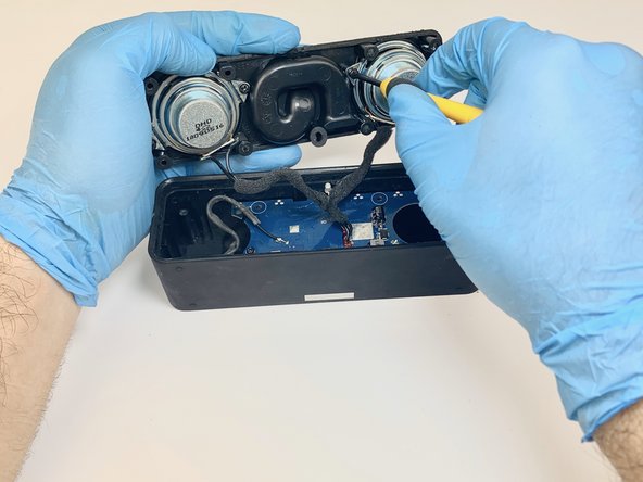
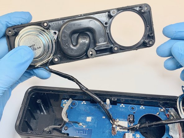
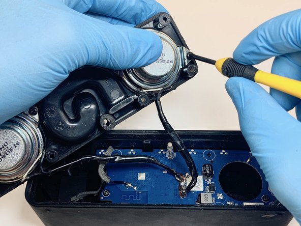
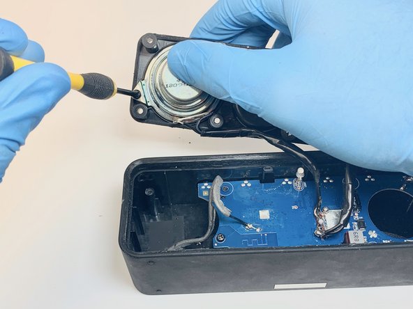
- Use a Phillips #1 screwdriver to remove the two 2mm screws from each of the speakers (four in total).
- The speakers may fall out of the housing upon removal of the four 2mm Phillip's head screws, be careful to not damage any parts of the motherboard or speaker housing if the speakers fall out.
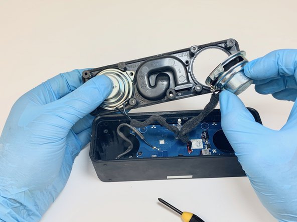
- Gently lift the speakers out of the housing.
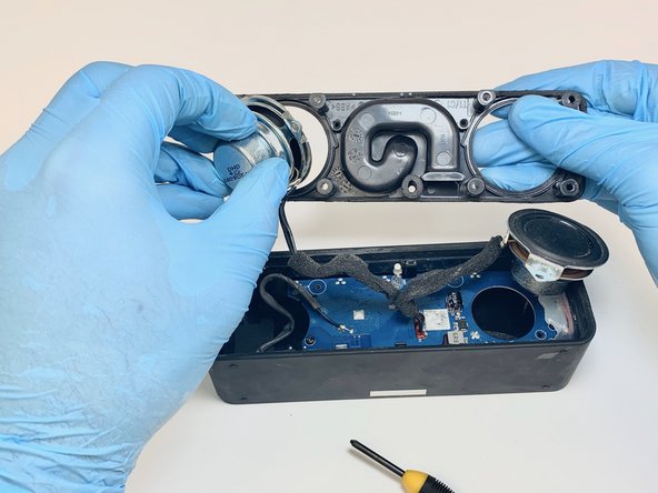
- The speakers are connected via a positive and negative wire. There are two wires per speaker, four in total.
- The wires are connected to the motherboard via soldering on the bottom of the motherboard.
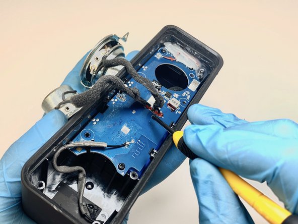
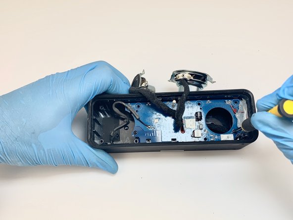
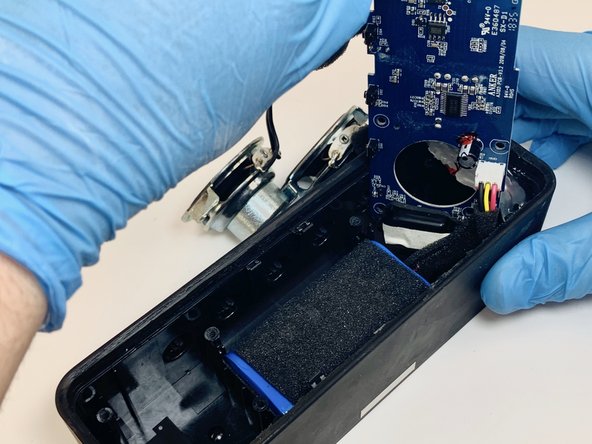
- Use a Phillips #1 screwdriver to remove the two 1mm screws holding down the motherboard.
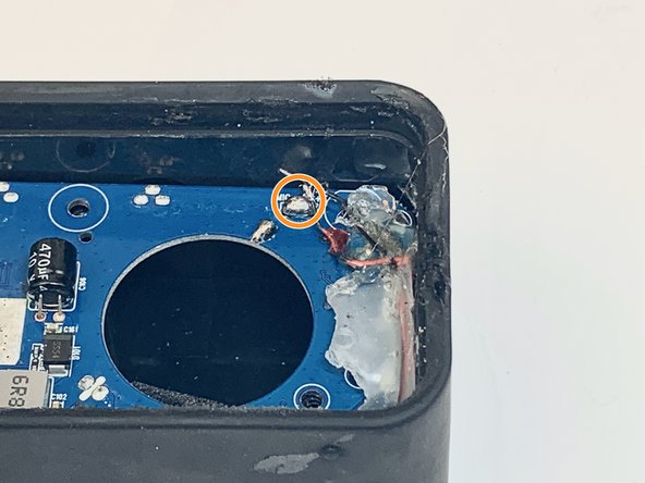
- The motherboard has hot glue holding a microphone wire and the motherboard in place.
- The motherboard cannot be removed yet and is still connected.
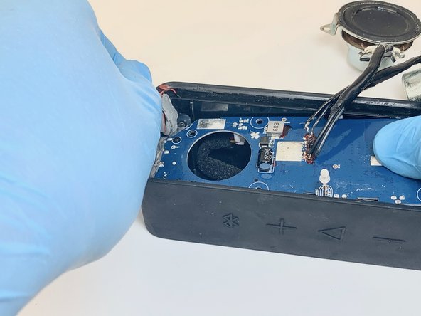
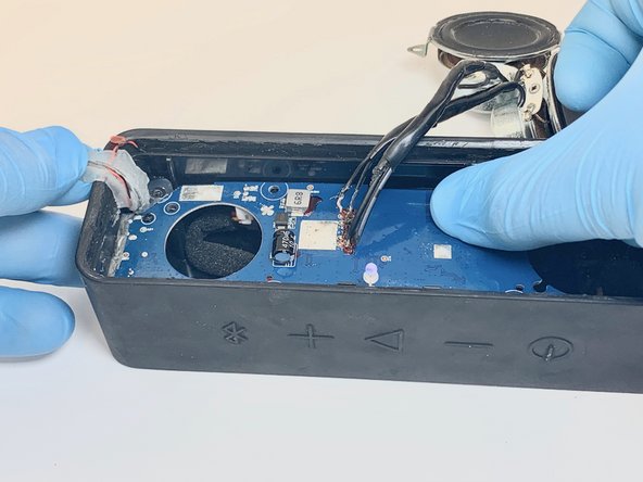
- Gently pull the ground wire on the left side of the motherboard, to remove it from the case.
- The ground wire can stay attached however it is recommended that it is removed.
- The ground wire might be hard to pull off so take caution when doing so to not damage it or the motherboard.
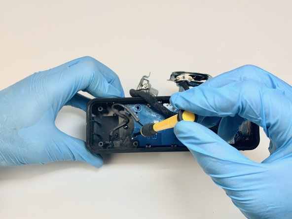
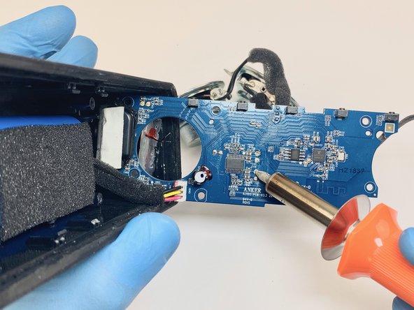
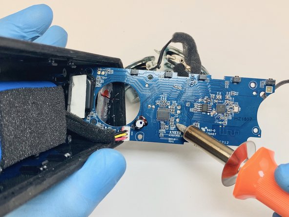
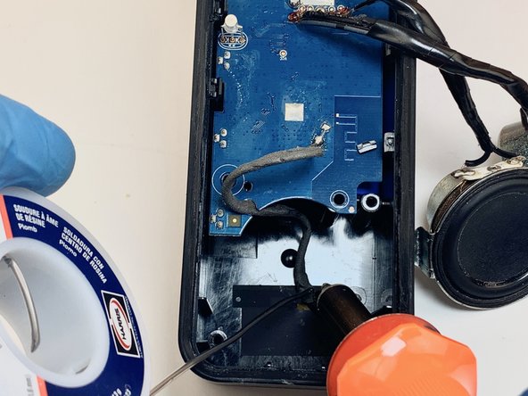
- To disconnect the microphone wire use the soldering iron and melt the solder connecting the wires to the motherboard.
- Gently lift the edges of the hot glue off the mother board.
- For help with soldering best practices, check out our How To Solder and Desolder Connections guide.
- Lifting the edges of the hot glue will help with the removal and reassembly of the motherboard.
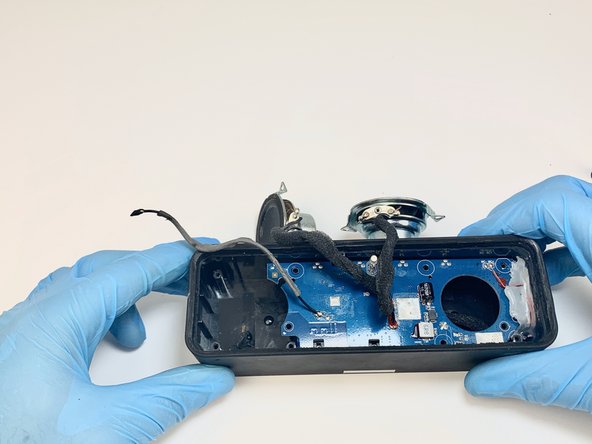
- Gently lift and pull out the motherboard slightly, being sure the wires on the back are not yanked out.
- It helps to hold the hot glue away while removing the motherboard.
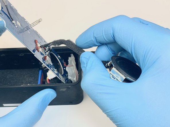
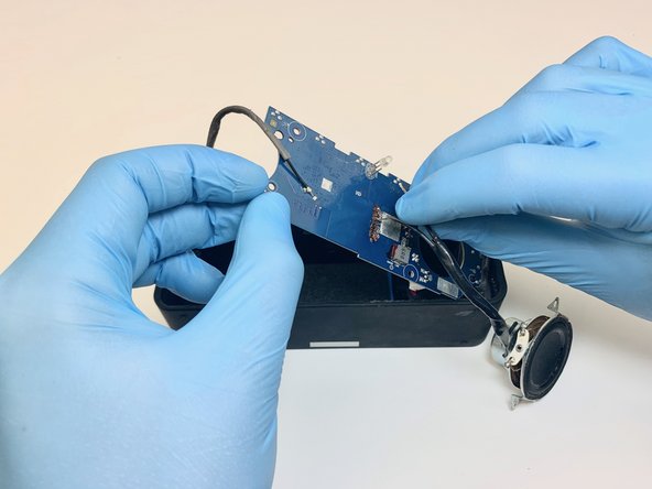
- To access the soldering holding the speakers to the motherboard, rotate the motherboard to where the backside is visible.
- The motherboard will still be connected to the speaker battery and won't be completely removed.
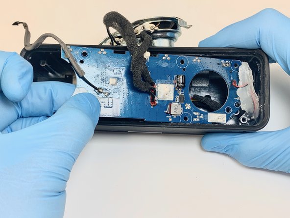
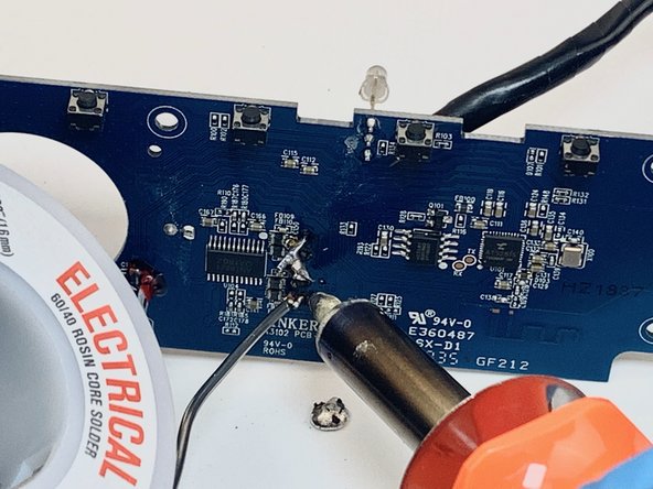
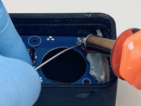
- Using the soldering iron, melt the four solder connections to free the speaker wires from the motherboard.
- Using the soldering iron, melt the solder connections to free the speaker wires.
- Do not damage the motherboard using the soldering iron.
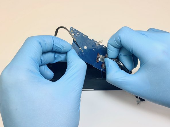
- Gently pull the wires away from the motherboard to remove and disconnect the speakers from the motherboard.
- Be gentle as the wires are thin and the motherboard is fragile, apply gentle pressure and the wires will pull out if properly desoldered.
- Insert the wires of the replacement speakers into the same holes the old speakers occupied.
- Do not damage or bend the wires when inserting them, go slow and ensure proper placement of the replacement speaker wires into the motherboard.
- Once the replacement speakers are in place it is time to solder the wires to ensure proper function and connection to the motherboard.
- Solder the four connections to the replacement speaker's wires poking out on the other side of the board.
- Soldering takes time and precision work with caution to not damage the motherboard by getting excess soldering on any other connections.
- Gently set the motherboard into the speaker case.
- It is important to ensure that the microphone wires, ground wire, and screws are located in the proper spots.
- It is helpful to hold the hot glue in the speaker case up while inserting the motherboard.
- To reconnect the ground wire you must solder the wire into place.
- Using the soldering iron and soldering wire, solder the ground wire into place.
- After soldering the ground wire into place, run the wire through the cutout in the motherboard.
- Solder the two microphone wires back onto the motherboard.
- It is important that the positive and negative wires are put in the proper spots, marked by the positive and negative symbols.
- Do not damage the motherboard or any other connections with the soldering iron or excess soldering wire.
- Replace the two 1mm Phillips #1 screws that hold down the motherboard.
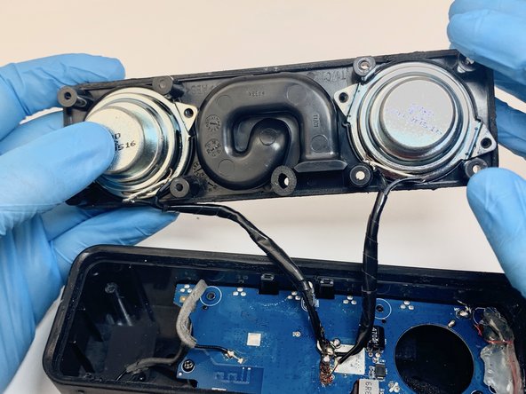
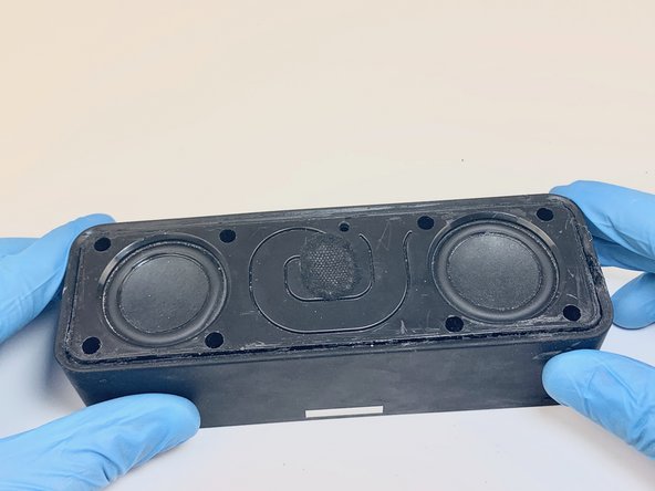
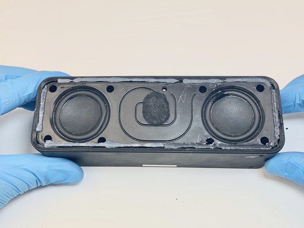
- Now, gently set the two replacement speakers into the black speaker housing ensuring that all screw holes are aligned.
- Align the speakers so they match the way we have it in the final picture.
- If placed in incorrectly further assembly will not be correct.
- Replace the four 2mm screws to affix the new speakers to the speaker housing with a Phillips #1 screwdriver.
- Be careful not to over-tighten the screws as it can strip the head of the screw or damage the housing.
- Gently set the speaker housing into the case. Apply small amounts of focused pressure to ensure proper seating of the speaker housing.
- Watch not to pinch the speaker wires upon reassembly. Take care to position them so they don't get damaged.
- Replace the eight 2mm screws to secure the speaker housing with a Phillips #1 screwdriver.
- Careful not to over tighten the screws as it can strip the head of the screw or damage the housing.
- During the removal of the metal grille it is normal for the grille to endure small bends.
- Straighten the grille for reassembly by gently applying pressure to the bent areas.
- The grille does not have to be perfectly straight as it will straighten fully during reassembly. However, the straighter the grille the easier the reassembly will be.
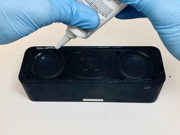
- Apply silicone glue to all four sides of the speaker housing along the speaker case.
- This will allow for a waterproof seal and proper reassembly of the speaker.
- It will help if you smooth the silicone out with your finger before inserting the grille.
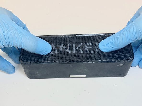
- Gently set the grille into the speaker housing and speaker case.
- Once the grille has been positioned properly, use firm pressure to seat the grille into the speaker housing and speaker case.
- The silicone will spread around the grille edges.
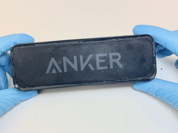
- Allow the glue to dry for the time recommended on the bottle, typically around 30-120 minutes.
- After reassembly the process is complete. This photo depicts the tools necessary to complete the guide.