iPod Touch 7th Generation Power Button Replacement
ID: 132231
Description: Use this guide to remove the power/sleep button...
Steps:
- If your display glass is cracked, keep further breakage contained and prevent bodily harm during your repair by taping the glass.
- Lay overlapping strips of clear packing tape over the iPod's display until the whole face is covered.
- This will keep glass shards contained and provide structural integrity when prying and lifting the display.
- Wear safety glasses to protect your eyes from any glass shaken free during the repair.
- Use a hairdryer or prepare an iOpener and apply it to the lower edge of the iPod for about a minute in order to soften up the adhesive underneath.
- The bottom of the screen (near the home button) is held in place with strong adhesive.
- As you start prying the screen off in the next stages, you may need to apply more heat to keep the glue warm and flexible.
- Center the suction cup on the lower section of the glass, with its edge centered over the home button.
- Press in firmly and make sure the cup has a strong seal.
- Hold the iPod firmly against a table or bench.
- Place your thumb and index finger over the lower corners of the display to stop the display from opening too far when the adhesive breaks.
- Lift the suction cup up and back toward the top of the iPod. Be patient, and pull with firm, constant force until the adhesive breaks and the display comes up from the rear case.
- It may be necessary to use a heat gun to soften the adhesive (especially in cooler climates). If you can pry the screen apart, and the adhesive is still sticking and pulling apart like cheese topping on a pizza, you can slide a thin razor blade in and gently cut the adhesive.
- After the display begins to lift from the rear case, be careful not to lift more than about an inch—a fragile plastic frame still connects the display assembly to the rear case.
- In the following steps, you will be loosening and freeing the plastic frame that surrounds the screen. It is connected to the rear case with several clips.
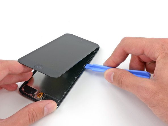
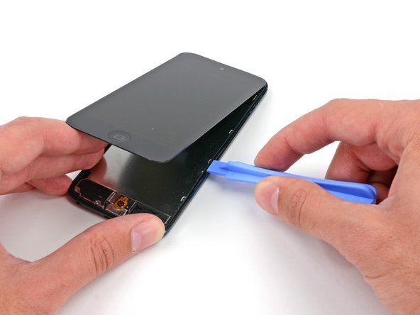
- Starting at the top right of the device, insert a plastic opening tool into the gap between the plastic frame and the aluminum rear case.
- Slide the tool down this crack, loosening the frame from the case.
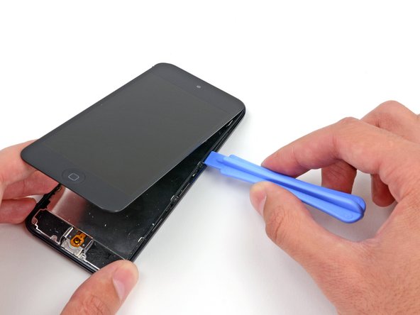
- Insert the plastic opening tool between the frame and the rear case behind the first clip.
- Rock the tool sideways, to spread the gap behind the clip and separate it from the rear case.
- This may not free the clip initially, but repeating the procedure for each clip will begin to loosen the piece.
- Repeat the procedure with the next two clips on this side.
- You may have to go back and forth between the clips to free all of them. Take your time and be careful and patient, as the plastic frame is quite fragile.
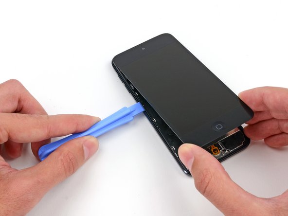
- Moving on to the left side of the device, insert a plastic opening tool into the gap between the plastic frame and the aluminum rear case near the top.
- Slide the tool down this crack, loosening the frame from the case.
- Insert the plastic opening tool between the frame and the rear case behind the first clip on the left side.
- Rock the tool sideways, to spread the gap behind the clip and separate it from the rear case.
- Repeat the procedure with the next two clips on this side.
- Insert the plastic opening tool between the plastic frame and aluminum rear case behind the second clip.
- Rock the tool sideways, loosening the clip from the case.
- Using the same procedure, loosen the last clip securing the plastic frame to the rear case.
- Insert the plastic opening tool between the display assembly and the rear case near the top of the iPod.
- Slightly twist the opening tool to pry the front panel up from the rear case.
- Separate the display assembly from the iPod.
- Do not try to completely remove the front panel, as it is still connected by several cables.
- Gently fold the display over away from the rest of the iPod, taking care not to disconnect or break any of the ribbon cables. Set the two halves flat on a table or bench.
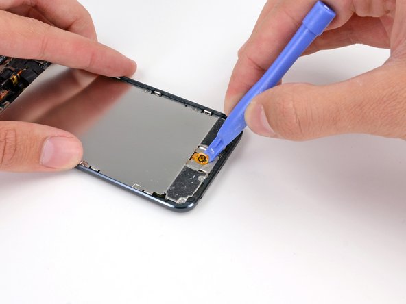
- If your iPod has a black home button assembly rather than the orange one shown here, you can skip this step. The button is not attached to the LCD plate and does not need to be removed to complete the repair.
- Use a plastic opening tool to pry the home button switch up from the LCD plate.
- It may be necessary to use a heat gun or hair dryer to soften the adhesive on the back of the home button. Always use a low heat setting.
- Do not attempt to remove the home button switch, as it is connected to components below the LCD plate.
- Remove the following screws securing the LCD plate to the rear case:
- Two 1.2 mm #000 Phillips screws
- Nine 1.6 mm #000 Phillips screws
- One 2.3 mm #000 Phillips screw
- Lift up and remove the LCD plate from the iPod.
- Remove three 1.6 mm #000 Phillips screws securing the logic board to the rear case.
- There are two strips of adhesive keeping the battery in place.
- Turn the iPod over and heat the BACK of the aluminium iPod case. Do not heat the battery.
- The aluminium case does not have to be hot; you should always be able to touch heated parts with your fingers at all times without it being uncomfortable.
- There are three notches on either side of the battery. In the next few steps, you will be using these notches to gradually pry the battery up from the rear case.
- The battery is secured with large amounts of adhesive, so you'll need to go slowly and carefully to avoid puncturing or creasing the battery.
- Insert a plastic opening tool into the top right notch and gently pry up on the battery.
- Do not attempt to pry up the entire battery at this point; you just want to start to loosen the adhesive at each of the prying points, in turn.
- Continue with the lower right notch. Insert the plastic opening tool into the notch, and gently pry up on the side of the battery.
- Continue prying the battery up from the bottom.
- When prying along the bottom, be careful not to press down too hard against the speaker or headphone jack.
- Pry along the left side as well.
- You may need to move back and forth between the sides and bottom of the battery, prying a small amount at a time until the battery is entirely free from the adhesive.
- Once all of the adhesive is loosened, lift the battery up from the bottom and swing it out over the left side of the rear case.
- Be sure not to yank it out, as it is soldered to the logic board.
- Flip the battery over to straighten its cable and set it down.
- Use the flat end of a spudger to flip the front-facing camera out of its socket in the display assembly.
- There is a small amount of adhesive securing the camera module to its socket, but this should not take very much force. Use the spudger to get in between the black plastic of the camera module and the black plastic of the camera socket and separate them.
- Use the tip of a spudger to peel back a small piece of tape covering a screw on the left side of the headphone jack.
- Remove the following screws securing the headphone jack, Lightning connector, and speaker.
- Three 2.6 mm #000 Phillips screws
- Two 2.0 mm #000 Phillips screws
- One 1.85 mm #000 Phillips screw
- Use the flat end of a spudger to pry the speaker up from the rear case.
- Do not try to remove the speaker, as it is soldered to the Lightning connector assembly.
- Grasping the large ribbon cable, gently pull the Lightning connector assembly out of the bottom of the case.
- Flip the entire assembly over, exposing the back of the logic board.
- Use a plastic opening tool to disconnect the digitizer cable from the logic board.
- Use a plastic opening tool to disconnect the display cable from its socket in the logic board.
- Flip the Lightning connector/logic board assembly back over to expose the top of the logic board.
- The display cable is lightly adhered to the top of the logic board.
- Use the flat end of a spudger to peel the display cable up from the logic board.
- Remove the display assembly from the iPod.
- Flip the logic board assembly back over to expose the connectors on the back.
- Use the edge of a plastic opening tool to gently pry the antenna connector off the back of the logic board.
- This cable is very delicate; be careful not to stress the point where it connects to the antenna.
- Disconnect the button ribbon cable connector from the back of the logic board.
- Use the edge of a plastic opening tool to disconnect the display connector from the back of the logic board.
- Remove the logic board assembly from the rear case of the iPod.
- Insert the flat end of a spudger between the rear-facing camera and its frame.
- Gently twist the spudger to free the camera.
- Lift the rear-facing camera up out of its socket, and remove it from the iPod Touch.
- Gently slide the flat end of a spudger underneath the piece of foam tape covering the button ribbon cable.
- Run the spudger along the full length of the tape to disconnect it from the rear case.
- Peel and remove the foam tape from the rear case of the iPod.
- Use the tip of a spudger to peel up the edge of the tape covering the button ribbon cable.
- Use tweezers or your fingers to peel the tape up from the rear case, and remove it from the iPod.
- Remove the following screws from the button ribbon cable:
- Two 2.3 mm #000 Phillips screws
- One 1.6 mm #000 Phillips screw
- Use tweezers to remove the small metal backing plate from the power switch section of the button ribbon cable.
- Insert a plastic opening tool into the rear-facing camera frame and pry up against the rear case.
- Twist the plastic opening tool slightly counter-clockwise to pry the camera frame up from the rear case.
- Use the closed tip of a pair of tweezers to push the power/sleep button into the rear case.
- Use tweezers to remove the power button from the iPod.