Breville Induction Cooker (LIC400BLKANZ) Teardown
ID: 132482
Description: The Breville Induction Cooker (LIC400BLK ANZ)...
Steps:
- Once you have your Breville Induction Cooker. You will notice the body is made up of an injection moulded ABS base and ceramic glass panel top. Let's take a closer look at the features on the top;
- A power Button
- Time Control
- 8 Cooking modes; sear, saute, medium, simmer, water boil, steam, slow cook, and, milk.
- A child Lock
- A keep warm
- A saucepan detecting area
- WARNING: UNPLUG the cooker before taking it apart. DO NOT TOUCH THE WHITE PUTTY, it is TOXIC thermal paste. If you do wash your hands thoroughly and limit contact with your face. You can clean the thermal paste off with rubbing alcohol.
- Now let's tear it down. Use a Phillips head screwdriver to undo the 6 screws found on the fringe of the back face. There are also 2 triangular screws located in the middle to be unscrewed (8 screws in total). Carefully flip the cooker so that the ceramic panel faces the top, then lift the panel to remove it from the case.
- Philips dome head screw x6 - M4x8mm
- Triangle dome head screw x2 - M4x10mm
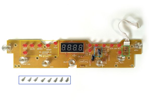
- Once open, you can locate the User Interface PCB (Printed Circuit Board). On this we can see;
- The timer
- Sensor buttons
- LED display
- Resistors
- Capacitors
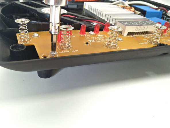
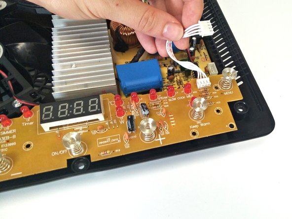
- To remove the user PCB, use the Philips head screwdriver to undo the 8 screws securing it to the base. Unclip the white wires that attach to the Main PCB before lifting the board out.
- Phillips round head screw x8 - M3x6mm
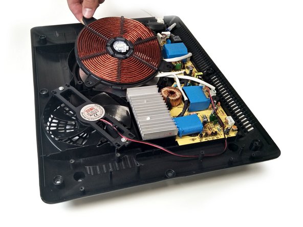
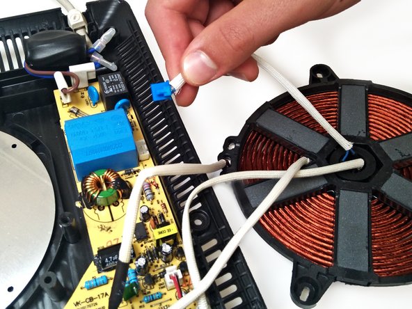
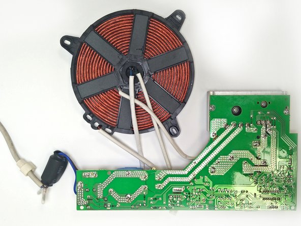
- Next locate the copper induction coil, which uses alternating current to create a magnetic field. Thus, creating heat by inducing a current.
- Use the Phillips head screwdriver, to undo the 3 screws holding the induction coil to the base. Remove each screw and their respective washers. Then lift it out and place beside the base.
- Dual Phillips/slotted round head screw x3 - M4x12mm
- Washers x3 - inner Ø 4mm, outer Ø 16mm
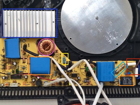
- To the right of the circuit is the Main PCB which powers the internal components. On this we can see;
- The AC power plugs
- Capacitors
- Resistors
- Microprocessors
- A fuse
- A heat sink
- Inductors
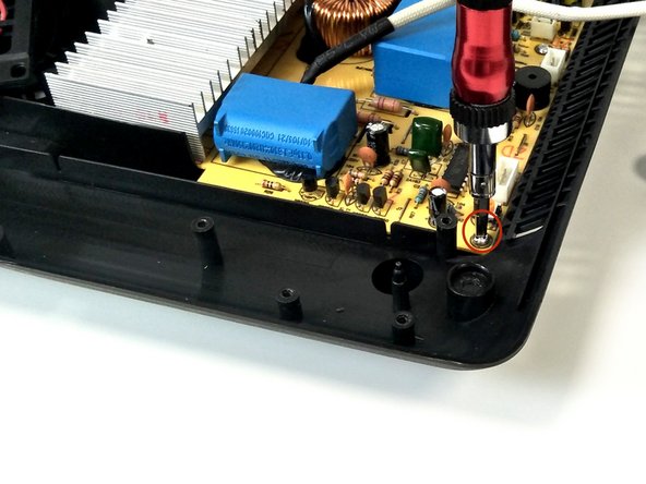
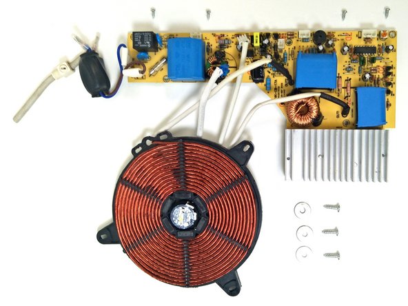
- To remove, use the Phillips head screwdriver to undo the 4 screws securing it to the base. Then gently pop all the chords out of the fasteners on the PCB. Once both the Induction coil and the Main PCB have been unscrewed, remove both.
- Phillips round head screw x4 - M3x6mm
- The aluminium heat sink, as we identified in Step 5 is a passive cooling device meaning it involves no electronics. The ribs provide surface area to allow air flow from the fan to help cool the inner components.
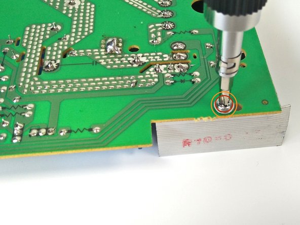
- To remove, flip the Main PCB upside down and use a Phillips head screwdriver to undo the 4 screws around the heat sink. Then lift from PCB
- Phillips washer head screw x2 - M3x10mm
- Phillips washer head screw x2 - M3x16mm
- WARNING: The thermal paste on the base of the heat sink and on the thread of the smaller screws is TOXIC. DO NOT TOUCH, if you do wash your hands thoroughly and limit contact with your face. You can clean the thermal paste off with rubbing alcohol.
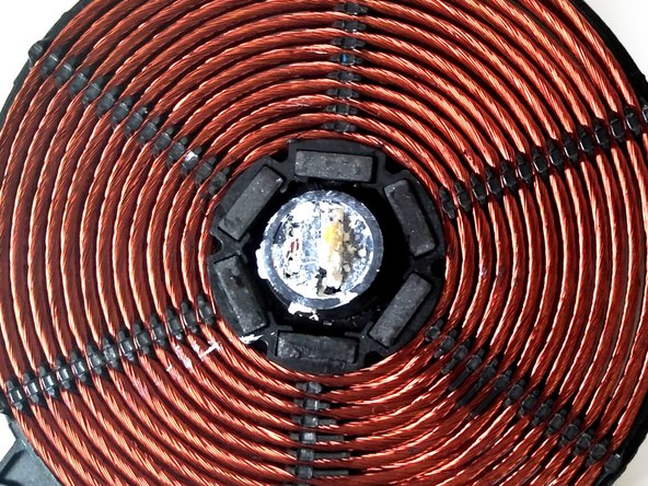
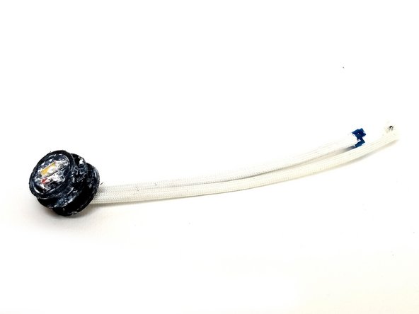
- In the centre of the coil there are two sensors, a temperature sensor and an electromagnetic wave sensor. Attached to the ceramic glass plate via the thermal paste.
- Carefully push the sensors rubber casing out of the induction coil.
- WARNING: The thermal paste on the sensors is TOXIC. DO NOT TOUCH, if you do wash your hands thoroughly and limit contact with your face. You can clean the thermal paste off with rubbing alcohol.
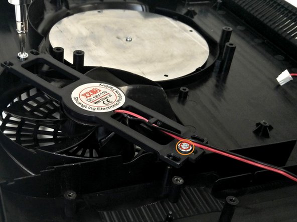
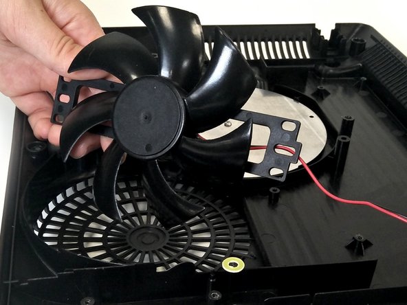
- Going back to the base locate the ABS fan, which cools the electrical components.
- Use the Phillips head screwdriver to undo the 2 screws. Remove each screw and their respective washers before lifting the fan from the base.
- Plastic washers x2 - inner Ø4mm, outer Ø10mm
- Phillips washer head screws x2 - M3x8mm
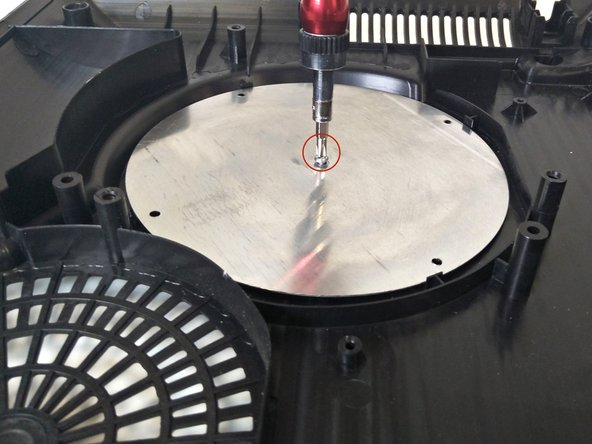
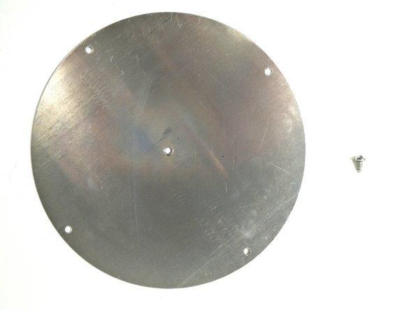
- Finally, where the induction coil was, there is a circular aluminium shield attached to the base. The shield prevents energy from the induction coil escaping downward.
- To remove simply use the Philips head screwdriver to undo the screw located at the centre. Lift the shield to remove it from the base.
- Phillips dome head screw x1 - M3x6mm
- Only a Phillips head and triangular head screwdriver are needed for the teardown.
- The Induction Cooker only has a few subassemblies that are easy to remove.
- Easy to understand when opened as the subassemblies are laid out well.
- The need of a triangular screwdriver may require purchasing extra equipment.
- Thermal paste on a lot of the parts makes working a safety hazard.
- This induction cooker is not the most recent version, thus replacement of parts may be scarce.